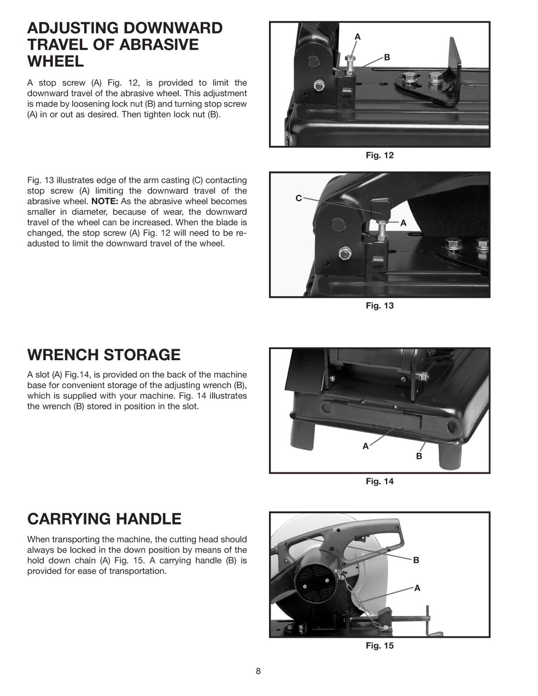
ADJUSTING DOWNWARD TRAVEL OF ABRASIVE WHEEL
A stop screw (A) Fig. 12, is provided to limit the downward travel of the abrasive wheel. This adjustment is made by loosening lock nut (B) and turning stop screw
(A) in or out as desired. Then tighten lock nut (B).
Fig. 13 illustrates edge of the arm casting (C) contacting stop screw (A) limiting the downward travel of the abrasive wheel. NOTE: As the abrasive wheel becomes smaller in diameter, because of wear, the downward travel of the wheel can be increased. When the blade is changed, the stop screw (A) Fig. 12 will need to be re- adusted to limit the downward travel of the wheel.
A
B
Fig. 12
C
A
Fig. 13
WRENCH STORAGE
A slot (A) Fig.14, is provided on the back of the machine base for convenient storage of the adjusting wrench (B), which is supplied with your machine. Fig. 14 illustrates the wrench (B) stored in position in the slot.
CARRYING HANDLE
When transporting the machine, the cutting head should always be locked in the down position by means of the hold down chain (A) Fig. 15. A carrying handle (B) is provided for ease of transportation.
A
B
Fig. 14
B
![]() A
A
Fig. 15
8