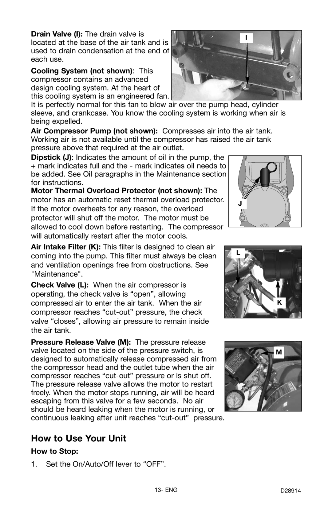
Drain Valve (I): The drain valve is |
| |
I | ||
located at the base of the air tank and is | ||
| ||
| ||
used to drain condensation at the end of |
| |
each use. |
|
Cooling System (not shown): This
compressor contains an advanced design cooling system. At the heart of
this cooling system is an engineered fan.
It is perfectly normal for this fan to blow air over the pump head, cylinder sleeve, and crankcase. You know the cooling system is working when air is being expelled.
Air Compressor Pump (not shown): Compresses air into the air tank. Working air is not available until the compressor has raised the air tank pressure above that required at the air outlet.
Dipstick (J): Indicates the amount of oil in the pump, the
+mark indicates full and the - mark indicates oil needs to be added. See Oil paragraphs in the Maintenance section for instructions.
Motor Thermal Overload Protector (not shown): The motor has an automatic reset thermal overload protector. If the motor overheats for any reason, the overload protector will shut off the motor. The motor must be allowed to cool down before restarting. The compressor will automatically restart after the motor cools.
Air Intake Filter (K): This filter is designed to clean air coming into the pump. This filter must always be clean and ventilation openings free from obstructions. See "Maintenance".
Check Valve (L): When the air compressor is operating, the check valve is “open”, allowing compressed air to enter the air tank. When the air compressor reaches
Pressure Release Valve (M): The pressure release valve located on the side of the pressure switch, is designed to automatically release compressed air from the compressor head and the outlet tube when the air compressor reaches
J
L
K
M
How to Use Your Unit
How to Stop:
1.Set the On/Auto/Off lever to “OFF”.
13- ENG | D28914 |