ASSEMBLY
Read this manual. Do not attempt to operate equipment until you have read this Manual for Safety, Operation, and
Maintenance Instructions.
NOTE: This manual is a general manual. Information in this manual may or may not pertain to your model. Please read carefully.
NOTE: Left and right describes the location of a part with the operator facing the outlet panel.
REMOVE GENERATOR FROM CARTON
•Open carton from top.
•Remove all carton inserts.
•Remove parts and manual kits and save for assembly.
•Cut down all four corners of the box and lay panels flat.
•Remove generator from carton.
•Discard all packaging.
OTHER LOOSE PARTS
1.Oil is supplied, see engine operator’s manual for correct procedure to add oil and fuel to engine.
IMPORTANT: Before any attempt to start your generator be sure to check engine oil (See Engine Operator's manual)
2.Parts kit containing: protective bar (1 used), extension cord wraps (2 used), rubber bumper (1 used), screw,
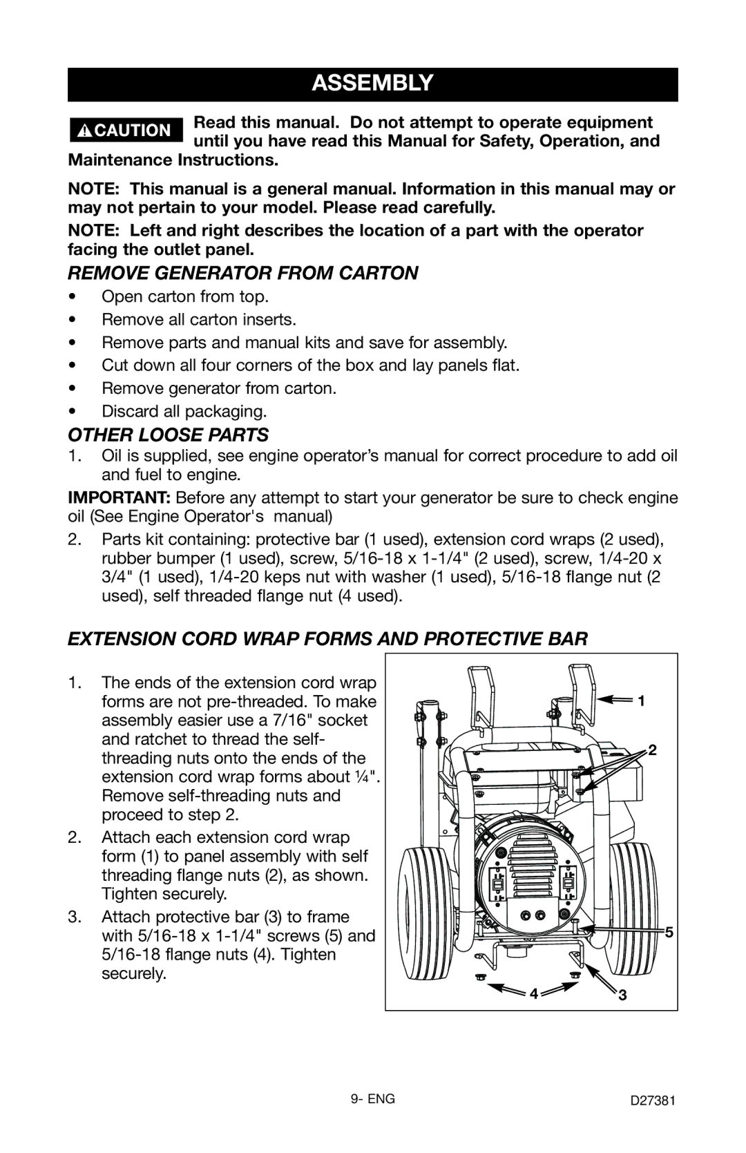
EXTENSION CORD WRAP FORMS AND PROTECTIVE BAR
1.The ends of the extension cord wrap forms are not
2.Attach each extension cord wrap form (1) to panel assembly with self threading flange nuts (2), as shown. Tighten securely.
3.Attach protective bar (3) to frame with
| 1 |
| 2 |
| 5 |
4 | 3 |
9- ENG | D27381 |
