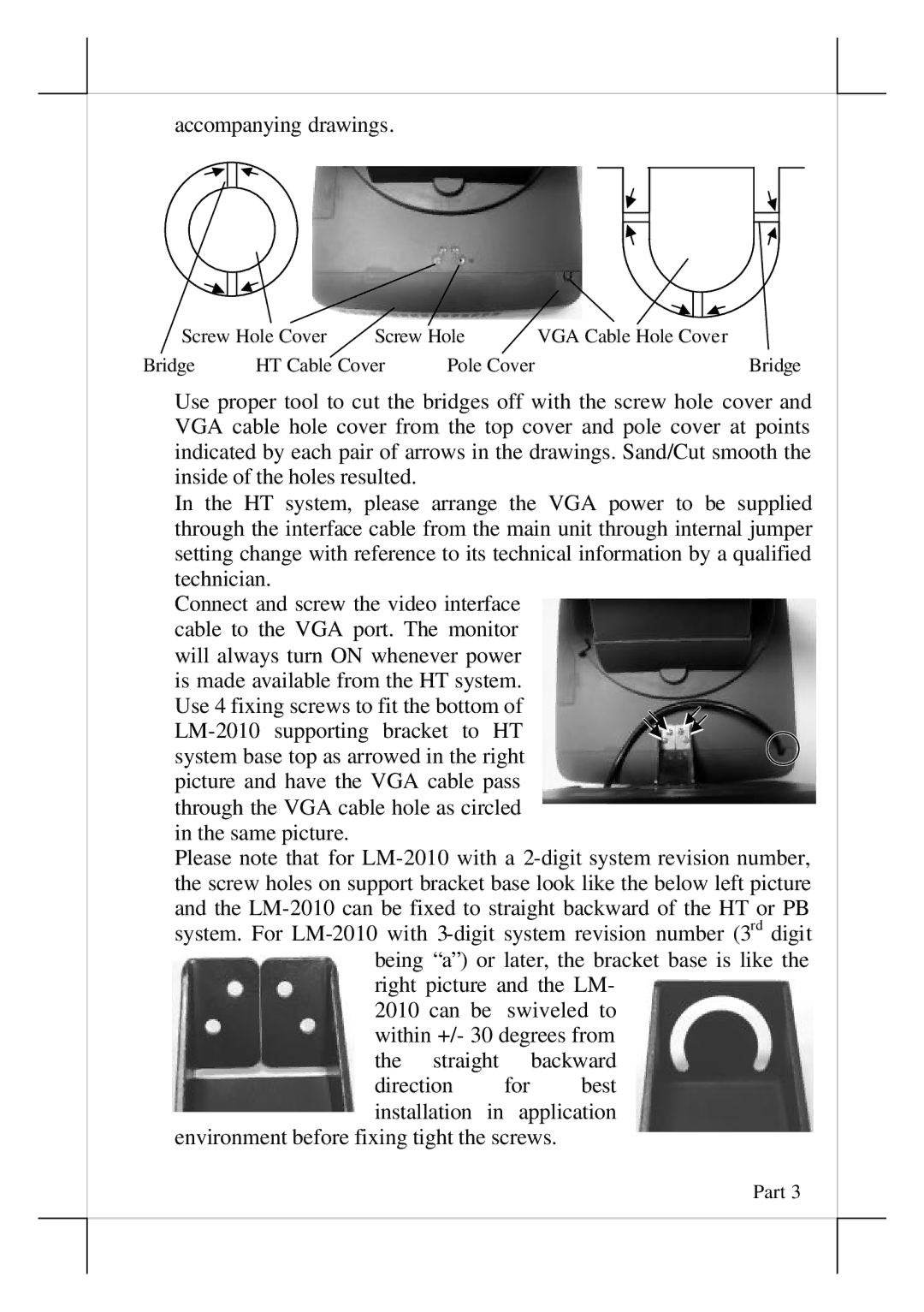
accompanying drawings.
Screw Hole Cover | Screw Hole | VGA Cable Hole Cover | ||
Bridge | HT Cable Cover | Pole Cover | Bridge | |
Use proper tool to cut the bridges off with the screw hole cover and VGA cable hole cover from the top cover and pole cover at points indicated by each pair of arrows in the drawings. Sand/Cut smooth the inside of the holes resulted.
In the HT system, please arrange the VGA power to be supplied through the interface cable from the main unit through internal jumper setting change with reference to its technical information by a qualified technician.
Connect and screw the video interface cable to the VGA port. The monitor will always turn ON whenever power is made available from the HT system. Use 4 fixing screws to fit the bottom of
picture and have the VGA cable pass through the VGA cable hole as circled in the same picture.
Please note that for
right picture and the LM-
2010 can be swiveled to within +/- 30 degrees from the straight backward
direction for best installation in application
environment before fixing tight the screws.
Part 3