1.Loosen the coupler by turning the knob counterclockwise.
Coupler
OPERATING INSTRUCTIONS
It is recommended that the engine not be operated for longer than 1 minute at full throttle.
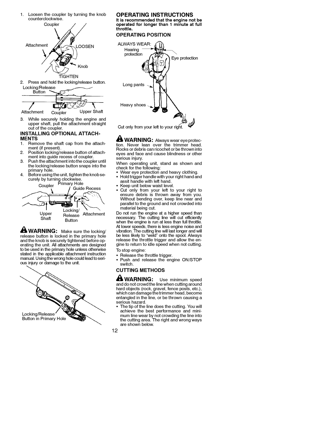
OPERATING POSITION
AttachmentLOOSEN
Knob
TIGHTEN
2.Press and hold the locking/release button. Locking/Release
Button
Attachment | Coupler | Upper Shaft |
ALWAYS WEAR:
Hearing ![]() protection
protection
Long pants
Heavy shoes
Eye protection
3.While securely holding the engine and upper shaft, pull the attachment straight out of the coupler.
INSTALLING OPTIONAL ATTACH- MENTS
1.Remove the shaft cap from the attach- ment (if present).
2.Position locking/release button of attach- ment into guide recess of coupler.
3.Push the attachment into the coupler until the locking/release button snaps into the primary hole.
4.Before using the unit, tighten the knob se- curely by turning clockwise.
Coupler Primary Hole
Guide Recess
Locking/
Upper Release Attachment
Shaft Button
![]() WARNING: Make sure the locking/ release button is locked in the primary hole and the knob is securely tightened before op- erating the unit. All attachments are designed to be used in the primary hole unless otherwise stated in the applicable attachment instruction manual. Using the wrong hole could lead to seri- ous injury or damage to the unit.
WARNING: Make sure the locking/ release button is locked in the primary hole and the knob is securely tightened before op- erating the unit. All attachments are designed to be used in the primary hole unless otherwise stated in the applicable attachment instruction manual. Using the wrong hole could lead to seri- ous injury or damage to the unit.
Locking/Release
Button in Primary Hole
Cut only from your left to your right.
![]() WARNING: Always wear eye protec- tion. Never lean over the trimmer head. Rocks or debris can ricochet or be thrown into eyes and face and cause blindness or other serious injury.
WARNING: Always wear eye protec- tion. Never lean over the trimmer head. Rocks or debris can ricochet or be thrown into eyes and face and cause blindness or other serious injury.
When operating unit, stand as shown and check for the following:
SWear eye protection and heavy clothing. S Hold trigger handle with your right hand and
assit handle with left hand. S Keep unit below waist level.
S Cut only from your left to your right to ensure debris is thrown away from you. Without bending over, keep line near and parallel to the ground and not crowded into material being cut.
Do not run the engine at a higher speed than necessary. The cutting line will cut efficiently when the engine is run at less than full throttle. At lower speeds, there is less engine noise and vibration. The cutting line will last longer and will be less likely to “weld” onto the spool. Always release the throttle trigger and allow the en- gine to return to idle speed when not cutting.
To stop engine:
SRelease the throttle trigger.
S Push and release the engine ON/STOP switch.
CUTTING METHODS
![]() WARNING: Use minimum speed and do not crowd the line when cutting around hard objects (rock, gravel, fence posts, etc.), which can damage the trimmer head, become entangled in the line, or be thrown causing a serious hazard.
WARNING: Use minimum speed and do not crowd the line when cutting around hard objects (rock, gravel, fence posts, etc.), which can damage the trimmer head, become entangled in the line, or be thrown causing a serious hazard.
SThe tip of the line does the cutting. You will achieve the best performance and mini- mum line wear by not crowding the line into the cutting area. The right and wrong ways are shown below.
12