ASSEMBLY
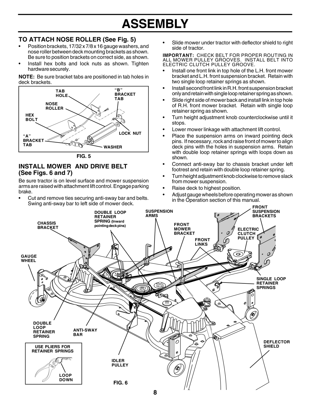
TO ATTACH NOSE ROLLER (See Fig. 5) |
| • Slide mower under tractor with deflector shield to right | |||
• Position brackets, 17/32 x 7/8 x 16 gauge washers, and | |||||
side of tractor. |
| ||||
nose roller between deck mounting brackets as shown. |
| ||||
IMPORTANT: CHECK BELT FOR PROPER ROUTING IN | |||||
Be sure to position brackets on correct side, as shown. | |||||
ALL MOWER PULLEY GROOVES. INSTALL BELT INTO | |||||
• Install hex bolts and lock nuts as shown. Tighten | |||||
ELECTRIC CLUTCH PULLEY GROOVE. | |||||
hardware securely. |
|
| • Install one front link in top hole of the L.H. front mower | ||
NOTE: Be sure bracket tabs are positioned in tab holes in | bracket and L.H. front suspension bracket. Retain with | ||||
deck brackets. |
|
| two single loop retainer springs as shown. | ||
TAB | “B” |
| • Install second front link in R.H. front suspension bracket | ||
| only and retain with single loop retainer spring as shown. | ||||
HOLE | BRACKET |
| |||
NOSE | TAB |
| • Slide right side of mower back and install link in top hole | ||
|
| of R.H. front mower bracket. Retain with single loop | |||
ROLLER |
|
| retainer spring as shown. |
| |
HEX |
|
|
| ||
|
| • Turn height adjustment knob counterclockwise until it | |||
BOLT |
|
| |||
|
| stops. |
| ||
|
|
|
| ||
| LOCK NUT |
| • Lower mower linkage with attachment lift control. | ||
“A” |
| • Place the suspension arms on inward pointing deck | |||
|
| ||||
BRACKET |
|
| pins. If necessary, rock and raise front of mower to align | ||
TAB | WASHER |
| deck pins with the holes in suspension arms. Retain | ||
|
| ||||
| FIG. 5 |
| with double loop retainer springs with loops down as | ||
|
| shown. |
| ||
INSTALL MOWER AND DRIVE BELT |
| • Connect | |||
(See Figs. 6 and 7) |
|
| footrest and retain with double loop retainer spring. | ||
|
| • Turn height adjustment knob clockwise to remove slack | |||
Be sure tractor is on level surface and mower suspension | |||||
from mower suspension. |
| ||||
arms are raised with attachment lift control. Engage parking | • Raise deck to highest position. | ||||
brake. |
|
| |||
|
| • Adjust gauge wheels before operating mower as shown | |||
• Cut and remove ties securing | |||||
in the Operation section of this manual. | |||||
Swing |
| ||||
|
| FRONT | |||
|
| SUSPENSION | |||
| DOUBLE LOOP | SUSPENSION | |||
| RETAINER | ARMS |
| BRACKETS | |
CHASSIS | SPRING (Inward |
| FRONT |
| |
pointing deck pins) |
|
| |||
BRACKET |
|
| |||
|
| MOWER | ELECTRIC | ||
|
|
| |||
|
|
| BRACKET | CLUTCH | |
|
|
| FRONT | PULLEY | |
|
|
|
| ||
|
|
| LINKS |
| |
GAUGE |
|
|
|
| |
WHEEL |
|
|
|
| |
|
|
|
| SINGLE LOOP | |
|
|
|
| RETAINER | |
|
|
|
| SPRINGS | |
DOUBLE
LOOP
RETAINER
SPRINGBAR
| DEFLECTOR |
USE PLIERS FOR | SHIELD |
RETAINER SPRINGS |
|
| IDLER |
| PULLEY |
LOOP
DOWN
FIG. 6
8