Sshield for use with trimmer head S semi-automatic trimmer head S shoulder strap with warning

S brush blade S handlebar

Examine parts for damage. Do not use dam- aged parts.

NOTE: If you need assistance or find that parts are missing or damaged, call 1-800-554-6723.

It is normal for the fuel filter to rattle in the empty fuel tank.

Finding fuel or oil residue on muffler is normal due to carburetor adjustments and testing done by the manufacturer.

ASSEMBLY

WARNING: If received assembled, repeat all steps to ensure your unit is properly assembled and all fasteners are secure.

TOOLS REQUIRED

S2 hex key wrenches (provided)

Sadjustable wrench or large pliers S phillips screwdriver

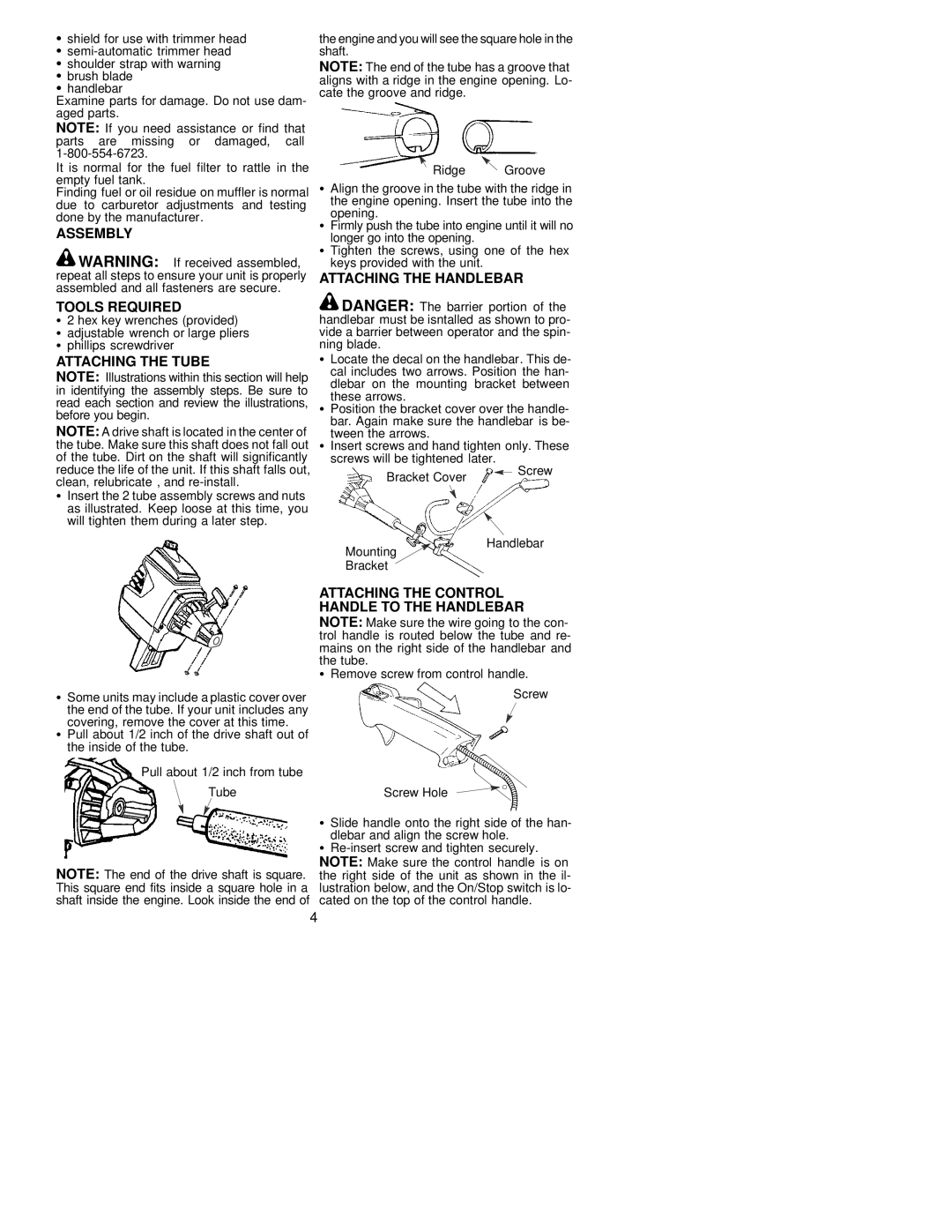
ATTACHING THE TUBE

NOTE: Illustrations within this section will help in identifying the assembly steps. Be sure to read each section and review the illustrations, before you begin.

NOTE: A drive shaft is located in the center of the tube. Make sure this shaft does not fall out of the tube. Dirt on the shaft will significantly reduce the life of the unit. If this shaft falls out, clean, relubricate , and re-install.

SInsert the 2 tube assembly screws and nuts as illustrated. Keep loose at this time, you will tighten them during a later step.

the engine and you will see the square hole in the shaft.

NOTE: The end of the tube has a groove that aligns with a ridge in the engine opening. Lo- cate the groove and ridge.

Ridge Groove

SAlign the groove in the tube with the ridge in the engine opening. Insert the tube into the opening.

SFirmly push the tube into engine until it will no longer go into the opening.

S Tighten the screws, using one of the hex keys provided with the unit.

ATTACHING THE HANDLEBAR

DANGER: The barrier portion of the handlebar must be isntalled as shown to pro- vide a barrier between operator and the spin- ning blade.

SLocate the decal on the handlebar. This de- cal includes two arrows. Position the han- dlebar on the mounting bracket between

these arrows.

SPosition the bracket cover over the handle- bar. Again make sure the handlebar is be-

tween the arrows.

SInsert screws and hand tighten only. These screws will be tightened later.

Bracket Cover


Screw


Mounting


Handlebar


Bracket


SSome units may include a plastic cover over

the end of the tube. If your unit includes any covering, remove the cover at this time.

SPull about 1/2 inch of the drive shaft out of the inside of the tube.

Pull about 1/2 inch from tube

Tube

NOTE: The end of the drive shaft is square. This square end fits inside a square hole in a shaft inside the engine. Look inside the end of

ATTACHING THE CONTROL HANDLE TO THE HANDLEBAR

NOTE: Make sure the wire going to the con- trol handle is routed below the tube and re- mains on the right side of the handlebar and the tube.

SRemove screw from control handle. Screw

Screw Hole

SSlide handle onto the right side of the han- dlebar and align the screw hole.

SRe-insert screw and tighten securely. NOTE: Make sure the control handle is on the right side of the unit as shown in the il- lustration below, and the On/Stop switch is lo- cated on the top of the control handle.

4

Page 4
Image 4
Poulan 530085855 manual Assembly Tools Required, Attaching the Tube, Attaching the Handlebar

530085855 specifications

The Poulan 530085855 is a versatile and powerful trimmer designed for homeowners and professionals alike who seek efficiency and ease of use in yard maintenance. This trimmer offers a unique blend of advanced features and technology, making it one of the standout models in the Poulan line.

One of the main features of the Poulan 530085855 is its robust engine, which typically boasts a displacement of 25cc. This powerful engine provides ample torque and performance to cut through various types of grass and weeds with ease. It delivers reliable starting power, allowing users to get to work quickly without the frustrating tug of a stubborn pull cord.

The trimmer is equipped with a dual-line feed system that allows for quick line advancement, enabling users to work efficiently without constant interruptions for line replacement. This feature is particularly beneficial for those who tackle larger yards or commercial properties, as it reduces the downtime significantly.

In addition to its powerful engine and effective line feed system, the Poulan 530085855 incorporates a strap and handle design that enhances user comfort during prolonged use. The adjustable handle provides better control and maneuverability around flower beds and hard-to-reach areas, resulting in a more productive trimming experience.

One of the standout technologies in the Poulan 530085855 is its anti-vibration system, which minimizes hand fatigue and discomfort during operation. This technology is essential for users who need to spend extended periods trimming, as it promotes user comfort and reduces the risk of strain or injury.

Furthermore, the Poulan 530085855 is designed with a lightweight frame, making it easy to handle and transport. Users appreciate this feature, especially when navigating different terrains or carrying the trimmer over longer distances.

Durability is another important characteristic of this trimmer. Constructed with high-quality materials, the Poulan 530085855 is built to withstand the rigors of outdoor use, making it a reliable choice for those who require consistent performance over time.

Overall, the Poulan 530085855 combines power, comfort, and durability, making it an excellent choice for anyone looking to maintain a well-groomed yard. Whether you are a professional landscaper or a homeowner wanting to keep your backyard neat, this trimmer provides the features and technologies necessary for efficient yard work. Its performance, coupled with user-friendly design elements, solidifies its position as a valuable tool for outdoor maintenance tasks.