STARTING A FLOODED ENGINE
Flooded engines can be started by placing the choke lever in the OFF CHOKE position; then, pull the rope to clear the engine of ex- cess fuel. This could require pulling the starter handle many times depending on how badly the unit is flooded.
If the unit still doesn’t start, refer to TROUBLESHOOTING TABLE or call
OPERATING THE COUPLER
This model is equipped with a coupler which enables optional attachments to be installed. The optional attachments are:
MODEL:
Edger . . . . . . . . . . . . . . . . . . . . . . PPB1000E Cultivator . . . . . . . . . . . . . . . . . . . PPB2000T Blower . . . . . . . . . . . . . . . . . . . . . PPB3000B Brushcutter . . . . . . . . . . . . . . . . . PPB4000C Pruner . . . . . . . . . . . . . . . . . . . . . PP5000P
![]() WARNING: Always stop unit anddis- connect spark plug before removing or instal- ling attachments.
WARNING: Always stop unit anddis- connect spark plug before removing or instal- ling attachments.
REMOVING TRIMMER ATTACH- MENT (OR OTHER OPTIONAL AT- TACHMENTS)
CAUTION: When removing or installing at- tachments, place the unit on a flat surface for stability.
1.Loosen the coupler by turning the knob counterclockwise.
Upper Shaft
Coupler
Coupler | Primary Hole |
| Guide Recess |
Upper | Locking/ Attachment |
Shaft | Release |
| Button |
![]() WARNING: Make sure the locking/ release button is locked in the primary hole and the knob is securely tightened before op- erating the unit.
WARNING: Make sure the locking/ release button is locked in the primary hole and the knob is securely tightened before op- erating the unit.
OPERATING INSTRUCTIONS
It is recommended that the engine not be operated for longer than 1 minute at full throttle.
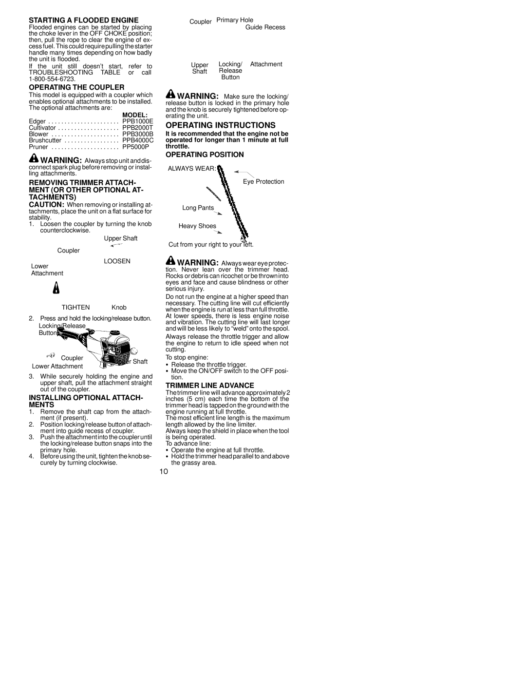
OPERATING POSITION
ALWAYS WEAR:
Eye Protection
Long Pants
Heavy Shoes
Cut from your right to your left.
Lower
LOOSEN
![]() WARNING: Always wear eye protec- tion. Never lean over the trimmer head.
WARNING: Always wear eye protec- tion. Never lean over the trimmer head.
Attachment
TIGHTEN Knob
2.Press and hold the locking/release button. Locking/Release
Button
Coupler | Upper Shaft | |
Lower Attachment | ||
|
3.While securely holding the engine and upper shaft, pull the attachment straight out of the coupler.
INSTALLING OPTIONAL ATTACH- MENTS
1.Remove the shaft cap from the attach- ment (if present).
2.Position locking/release button of attach- ment into guide recess of coupler.
3.Push the attachment into the coupler until the locking/release button snaps into the primary hole.
4.Before using the unit, tighten the knob se- curely by turning clockwise.
Rocks or debris can ricochet or be throwninto eyes and face and cause blindness or other serious injury.
Do not run the engine at a higher speed than necessary. The cutting line will cut efficiently whenthe engine is run at less than full throttle. At lower speeds, there is less engine noise and vibration. The cutting line will last longer and will be less likely to “weld” onto the spool.
Always release the throttle trigger and allow the engine to return to idle speed when not cutting.
To stop engine:
SRelease the throttle trigger.
SMove the ON/OFF switch to the OFF posi- tion.
TRIMMER LINE ADVANCE
Thetrimmer line will advance approximately 2 inches (5 cm) each time the bottom of the trimmer head is tapped on the ground with the engine running at full throttle.
The most efficient line length is the maximum length allowed by the line limiter.
Always keep the shield in place when the tool is being operated.
To advance line:
SOperate the engine at full throttle.
SHold the trimmer head parallel to and above the grassy area.
10