from water heaters, electric motors or switches, furnaces, etc.
SStore unit so the blade cannot accidentally cause injury.
SStore unit indoors, out of reach of children. If situations occur which are not covered in this manual, use care and good judgment. If you need assistance, call
SPECIALNOTICE:Exposure to vibrations through prolonged use of gasoline powered hand tools could cause blood vessel or nerve damage in the fingers, hands, and joints of people proneto circulation disorders or abnor- mal swellings. Prolonged use in cold weather
has been linked to blood vessel damage in otherwise healthy people. If symptoms occur such as numbness, pain, loss of strength, change in skin color or texture, or loss of feel- ing in the fingers, hands, or joints, discontinue the use of this tool and seek medical attention. An
SAVE THESE INSTRUCTIONS
CARTON CONTENTS
Check carton contents for the following:
SBrushcutter attachment
SHandlebar (with clamp and knob)
SHandlebar clamp base (with spacer tabs) S Shoulder strap
S Upper shoulder strap clamp
S Lower shoulder strap clamp (with spacer tabs) S Handlebar clamp screws (4)
S Shoulder strap clamp screws (2)
S
S Large nut for installing blade S Retaining washer
S Cupped washer
S Metal shield (assembled on brushcutter at- tachment)
S Trimmer head S Plastic shield
S Wing nut (screwed onto plastic shield) S Attachment hanger
S Hex wrench
![]() WARNING: If received assembled, re- peat all steps to ensure your unit is properly as- sembled and all fasteners are secure.
WARNING: If received assembled, re- peat all steps to ensure your unit is properly as- sembled and all fasteners are secure.
Examine parts for damage. Do not use dam- aged parts.
NOTE:If you need assistance or find that parts are missing or damaged, call
TOOLS REQUIRED
SHex wrench (provided)
INSTALLING BRUSHCUTTER ATTACHMENT
CAUTION: When removing or installing at- tachments, place the unit on a flat surface for
stability.
1.Loosen the coupler by turning the knob counterclockwise.
Coupler
LOOSEN
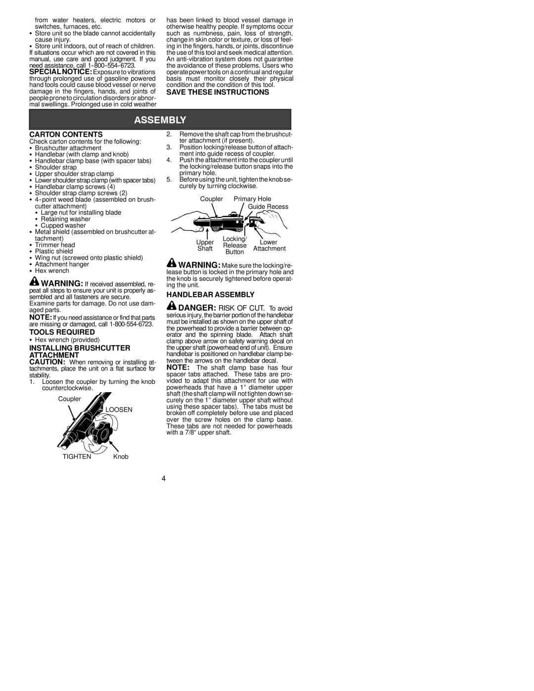
2.Remove the shaft cap from the brushcut- ter attachment (if present).
3.Position locking/release button of attach- ment into guide recess of coupler.
4.Push the attachment into the coupler until the locking/release button snaps into the primary hole.
5.Before using the unit, tightenthe knob se- curely by turning clockwise.
Coupler | Primary Hole | ||
|
| Guide Recess | |
Upper | Locking/ | Lower | |
Release | |||
Shaft | Attachment | ||
| Button |
| |
![]() WARNING: Make sure the locking/re- lease button is locked in the primary hole and the knob is securely tightened before operat- ing the unit.
WARNING: Make sure the locking/re- lease button is locked in the primary hole and the knob is securely tightened before operat- ing the unit.
HANDLEBAR ASSEMBLY
![]() DANGER: RISK OF CUT. To avoid serious injury, the barrier portion of the handlebar must be installed as shown on the upper shaft of the powerhead to provide a barrier between op- erator and the spinning blade. Attach shaft clamp above arrow on safety warning decal on the upper shaft (powerhead end of unit). Ensure handlebar is positioned on handlebar clamp be- tween the arrows on the handlebar decal.
DANGER: RISK OF CUT. To avoid serious injury, the barrier portion of the handlebar must be installed as shown on the upper shaft of the powerhead to provide a barrier between op- erator and the spinning blade. Attach shaft clamp above arrow on safety warning decal on the upper shaft (powerhead end of unit). Ensure handlebar is positioned on handlebar clamp be- tween the arrows on the handlebar decal.
NOTE: The shaft clamp base has four spacer tabs attached. These tabs are pro- vided to adapt this attachment for use with powerheads that have a 1∀ diameter upper shaft (the shaft clamp will not tighten down se- curely on the 1∀ diameter upper shaft without using these spacer tabs). The tabs must be broken off completely before use and placed over the screw holes on the clamp base. These tabs are not needed for powerheads with a 7/8∀ upper shaft.
TIGHTEN Knob
4