ATTACHING THE CONTROL HANDLE TO THE HANDLEBAR
NOTE: Make sure the wire going to the con- trol handle is routed below the tube and re- mains on the right side of the handlebar and the tube.
Screw
Screw Hole
terial. Go to the section for the desired configuration and follow the instructions for assembling your unit.
ASSEMBLY INFORMATION - TRIMMER HEAD
TRIMMER
HEAD
SSlide handle onto the right side of the han-
dlebar and align the screw hole.
SInsert screw and tighten securely. NOTE: Make sure the control handle is on the right side of the unit as shown in the il- lustration below, and the On/Stop switch is lo- cated on the top of the control handle.
S Adjust the handlebar to the proper position and tighten the two screws you left loose during handlebar assembly. Make sure these screws are securely tightened.
S After attaching the control handle and tight- ening the handlebar, route the wire from the control handle through the slit in the bottom of the foam grip.
Foam Grip
Slit Wire
ASSEMBLY OF SHOULDER STRAP
![]() WARNING: Proper shoulder strap and handlebar adjustments before starting the engine are required.
WARNING: Proper shoulder strap and handlebar adjustments before starting the engine are required.
STry on shoulder strap and adjust for fit and
balance before starting the engine or begin- ning a cutting operation.
NOTE: If your unit has been assembled for brushblade use, refer to the section AS-
SEMBLY INFORMATION FOR USING YOUR UNIT WITH A BRUSH BLADE and re- verse the steps to remove the metal shield and blade before you mount the plastic shield and trimmer head.
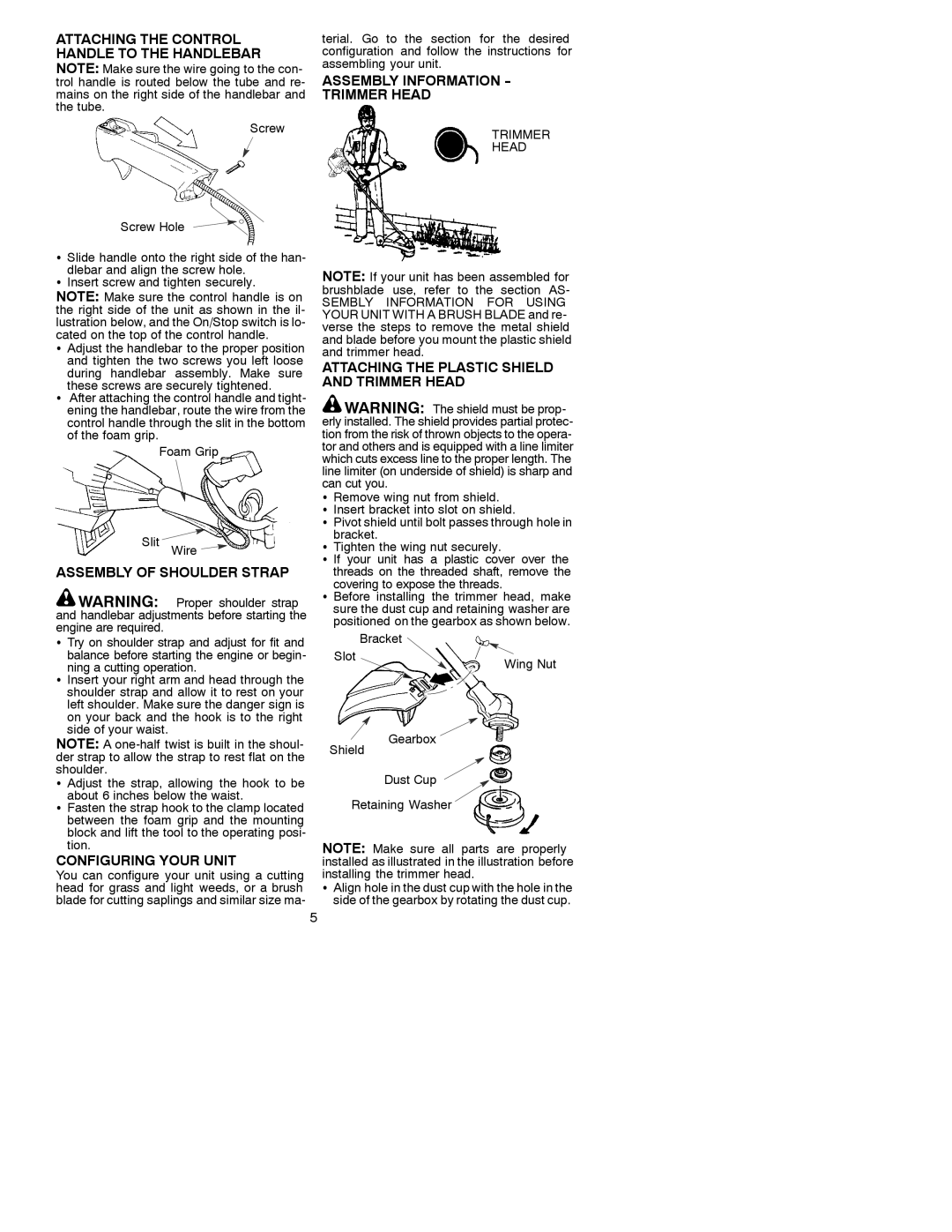
ATTACHING THE PLASTIC SHIELD AND TRIMMER HEAD
![]() WARNING: The shield must be prop- erly installed. The shield provides partial protec- tion from the risk of thrown objects to the opera- tor and others and is equipped with a line limiter which cuts excess line to the proper length. The line limiter (on underside of shield) is sharp and can cut you.
WARNING: The shield must be prop- erly installed. The shield provides partial protec- tion from the risk of thrown objects to the opera- tor and others and is equipped with a line limiter which cuts excess line to the proper length. The line limiter (on underside of shield) is sharp and can cut you.
SRemove wing nut from shield.
SInsert bracket into slot on shield.
SPivot shield until bolt passes through hole in bracket.
STighten the wing nut securely.
S If your unit has a plastic cover over the threads on the threaded shaft, remove the covering to expose the threads.
S Before installing the trimmer head, make sure the dust cup and retaining washer are positioned on the gearbox as shown below.
Bracket
Slot | Wing Nut |
|
SInsert your right arm and head through the shoulder strap and allow it to rest on your left shoulder. Make sure the danger sign is on your back and the hook is to the right side of your waist.
NOTE: A
Shield
Gearbox
S Adjust the strap, allowing the hook to be about 6 inches below the waist.
SFasten the strap hook to the clamp located between the foam grip and the mounting block and lift the tool to the operating posi- tion.
CONFIGURING YOUR UNIT
You can configure your unit using a cutting head for grass and light weeds, or a brush blade for cutting saplings and similar size ma-
5
Dust Cup
Retaining Washer
NOTE: Make sure all parts are properly installed as illustrated in the illustration before installing the trimmer head.
SAlign hole in the dust cup with the hole in the side of the gearbox by rotating the dust cup.