S WHAT CAUSES BLADE THRUST Blade Thrust can occur when the spinning blade contacts an object that it does not cut. This contact causes the blade to stop for an instant and then suddenly move or “thrust” away from the object that was hit. The “thrusting” reaction can be violent enough to cause the operator to be propelled in any direction and lose control of the unit. The uncontrolled unit can cause serious injury if the blade contacts the operator or others.
SWHEN BLADE THRUST OCCURS. Blade thrust can occur without warning if the blade snags, stalls, or binds. This is more likely to occur in areas where it is difficult to see the material being cut. By using the unit prop- erly, the occurrence of blade thrust will be reduced and the operator will be less likely to lose control.
SCut only grass, weeds, and woody brush up to 2 inches in diameter with the brush blade. Do not let the blade contact material it can- not cut such as stumps, rocks, fences, metal, etc., or clusters of hard, woody brush
having a diameter greater than 2 inches.
SKeep the blade sharp. A dull blade is more likely to snag and thrust.
SCut only at full throttle. The blade will have maximum cutting power and is less likely to
bind or stall.
S “Feed” the blade deliberately and not too rapidly. The blade can thrust away if it is fed too rapidly.
SCut only from your right to your left. Swing-
ing the unit in the same direction as the blade spins increases the cutting action.
SUse the shoulder strap and keep a firm grip on the unit with both hands. A properly ad- justed shoulder strap will support the weight of the unit, freeing your arms and hands to
control and guide the cutting motion.
S Keep feet comfortably spread apart and braced for a possible sudden, rapid thrust of unit. Do not overreach. Keep firm footing and balance.
SKeep blade below waist level; it will be eas- ier to maintain control of unit.
SDo not raise the engine above your waist as the blade can come dangerously close to
your body.
SDo not swing unit with such force that you are in danger of losing your balance.
Bring the engine to cutting speed before enter- ing the material to be cut.
If the blade does not turn when you squeeze the throttle trigger, make sure tube is fully in- serted into the engine.
Always release the throttle trigger and allow engine to return to idle speed when not cutting.
The blade should not turn while the engine is running at idle. If the blade turns at idle, do not use your unit. Refer to the Carburetor adjust- ment section or contact your Authorized Ser- vice Dealer.
10 o’clock
Cut using the 8 o’clock to 10 o’clock position of the blade
8 o’clock
![]() WARNING: The operator or others must not try to clear away cut material with the engine running or the blade turning to avoid serious injury. Stop engine and blade before removing materials wrapped around blade or tube.
WARNING: The operator or others must not try to clear away cut material with the engine running or the blade turning to avoid serious injury. Stop engine and blade before removing materials wrapped around blade or tube.
REPLACING THE LINE
![]() WARNING: Trimmer head parts that are chipped, cracked, broken, or damaged in any other way can fly apart and cause serious injury. Do not use. Replace damaged parts be- fore using unit.
WARNING: Trimmer head parts that are chipped, cracked, broken, or damaged in any other way can fly apart and cause serious injury. Do not use. Replace damaged parts be- fore using unit.
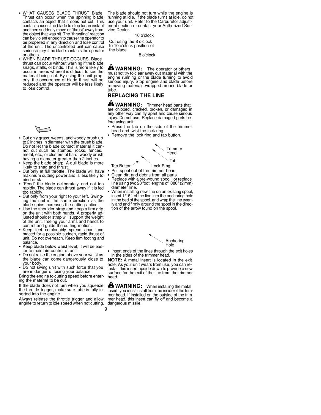
S Press the tab on the side of the trimmer head and twist the lock ring.
SRemove the lock ring and tap button.
|
|
|
|
|
|
|
|
| Trimmer |
|
|
|
|
|
|
|
|
| Head |
|
|
|
|
|
|
|
|
| Tab |
|
|
|
|
|
|
|
|
| |
Tap Button |
| Lock Ring | |||||||
SPull spool out of the trimmer head. S Clean dirt and debris from all parts.
S Replace with a
S When installing new line on an existing spool, insert 1/16I of the line into the anchoring hole in the bed of the spool, and wrap the line even- ly and and firmly around the spool in the direc- tion of the arrow found on the spool.
Anchoring
Hole
SInsert ends of the lines through the exit holes in the sides of the trimmer head.
NOTE: A metal insert is located in the exit hole. As your unit wears from use, you can re- install this insert upside down to provide a new surface for the exit of the line from the trimmer head.
![]() WARNING: When installing the metal insert, you must install from the inside of the trim- mer head. If installed on the outside of the trim- mer head, this insert can fly off and become a dangerous missile.
WARNING: When installing the metal insert, you must install from the inside of the trim- mer head. If installed on the outside of the trim- mer head, this insert can fly off and become a dangerous missile.
9