2.Position the bracket cover over the han- dlebar. Again make sure the handlebar is at the end of the arrow.
3.Insert screws and hand tighten only. Be sure the handlebar is installed correctly; then, tighten each screw securely with the hex wrench.
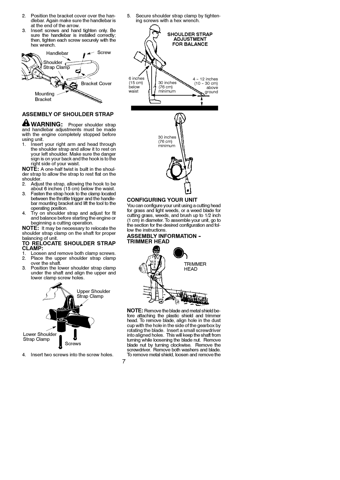
Handlebar ![]() Screw
Screw
Shoulder
Strap Clamp
Bracket Cover
Mounting ![]()
Bracket
5.Secure shoulder strap clamp by tighten- ing screws with a hex wrench.
SHOULDER STRAP
ADJUSTMENT
FOR BALANCE
6 inches |
|
| 4 |
(15 cm) |
| 30 inches | (10 |
below |
| (76 cm) | above |
waist |
| minimum | ground |
|
|
|
|
ASSEMBLY OF SHOULDER STRAP
![]() WARNING: Proper shoulder strap and handlebar adjustments must be made with the engine completely stopped before using unit.
WARNING: Proper shoulder strap and handlebar adjustments must be made with the engine completely stopped before using unit.
1.Insert your right arm and head through the shoulder strap and allow it to rest on your left shoulder. Make sure the danger sign is on your back and the hook is to the right side of your waist.
NOTE: A
2.Adjust the strap, allowing the hook to be about 6 inches (15 cm) below the waist.
3.Fasten the strap hook to the clamp located between the throttle trigger and the handle- bar mounting bracket and lift the tool to the operating position.
4.Try on shoulder strap and adjust for fit and balance before starting the engine or beginning a cutting operation.
NOTE: It may be necessary to relocate the shoulder strap clamp on the shaft for proper balancing of unit.
TO RELOCATE SHOULDER STRAP CLAMP:
1.Loosen and remove both clamp screws.
2.Place the upper shoulder strap clamp over the shaft.
3.Position the lower shoulder strap clamp under the shaft and align the upper and lower clamp screw holes.
30inches
(76 cm) minimum
CONFIGURING YOUR UNIT
You can configure your unit using a cutting head for grass and light weeds, or a weed blade for cutting grass, weeds, and brush up to 1/2 inch (1 cm) in diameter. To assemble your unit, go to the section for the desired configuration and fol- low the instructions.
ASSEMBLY INFORMATION - TRIMMER HEAD
TRIMMER
HEAD
Lower Shoulder Strap Clamp
Upper Shoulder
Strap Clamp
Screws
NOTE: Remove the blade and metal shield be- fore attaching the plastic shield and trimmer head. To remove blade, align hole in the dust cup with the hole in the side of the gearbox by rotating the blade. Insert a small screwdriver into aligned holes. This will keep the shaft from turning while loosening the blade nut. Remove blade nut by turning clockwise. Remove the screwdriver. Remove both washers and blade.
4. Insert two screws into the screw holes.
To remove metal shield, loosen and remove the
7