ASSEMBLY / PRE-OPERATION
1.Slide rubber sleeve up rod and hook end of spring into control arm with loop opening up as shown.
2.With top end of rod positioned under right side of control panel, push down on rod and insert end of rod into hole in auger control bracket. Secure with retainer spring.
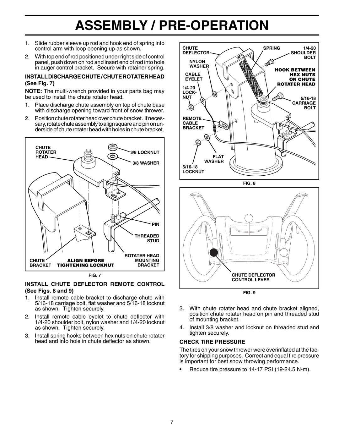
INSTALL DISCHARGE CHUTE / CHUTE ROTATER HEAD (See Fig. 7)
NOTE: The
1.Place discharge chute assembly on top of chute base with discharge opening toward front of snow thrower.
2.Position chute rotater head over chute bracket. If neces- sary, rotate chute assembly to align square and pin on un- derside of chute rotater head with holes in chute bracket.
CHUTE |
|
|
ROTATER |
| 3/8 LOCKNUT |
HEAD |
|
|
|
| 3/8 WASHER |
|
| PIN |
|
| THREADED |
|
| STUD |
| ALIGN BEFORE | ROTATER HEAD |
CHUTE | MOUNTING | |
BRACKET | TIGHTENING LOCKNUT | BRACKET |
FIG. 7
INSTALL CHUTE DEFLECTOR REMOTE CONTROL (See Figs. 8 and 9)
1.Install remote cable bracket to discharge chute with
2.Install remote cable eyelet to chute deflector with
3.Install spring hooks between hex nuts on chute rotater head and into hole in chute deflector as shown.
CHUTE | SPRING | ||
DEFLECTOR |
| SHOULDER | |
NYLON |
| BOLT | |
|
| ||
WASHER | HOOK BETWEEN | ||
CABLE | |||
| HEX NUTS | ||
EYELET |
| ON CHUTE | |
ROTATER HEAD | |||
|
| ||
LOCK- |
|
| |
NUT |
| ||
|
| CARRIAGE | |
|
| BOLT | |
REMOTE |
|
| |
CABLE |
|
| |
BRACKET |
|
| |
FLAT |
|
| |
WASHER |
|
| |
|
| ||
LOCKNUT |
|
| |
FIG. 8
CHUTE DEFLECTOR |
CONTROL LEVER |
FIG. 9
3.With chute rotater head and chute bracket aligned, position chute rotater head on pin and threaded stud of mounting bracket.
4.Install 3/8 washer and locknut on threaded stud and tighten securely.
CHECK TIRE PRESSURE
The tires on your snow thrower were overinflated at the fac- tory for shipping purposes. Correct and equal tire pressure is important for best snow throwing performance.
•Reduce tire pressure to
7