INSPECT AND CLEAN UNIT AND DE- CALS
S After each use, inspect complete unit for loose or damaged parts. Clean the unit and decals using a damp cloth with a mild deter- gent.
SWipe off unit with a clean dry cloth.
CLEAN AIR FILTER
A dirty air filter decreases engine perform- ance and increases fuel consumption and harmful emissions. Always clean after every 5 hours of operation.
1. Clean the cover and the area around it to keep dirt from falling into the carburetor chamber when the cover is removed.
2. Remove parts by pressing button to re- lease air filter cover.
NOTE: To avoid creating a fire hazard or producing harmful evaporative emissions, do not clean filter in gasoline or other flammable solvent.
3.Wash the filter in soap and water.
4.Allow filter to dry.
5.Replace parts.
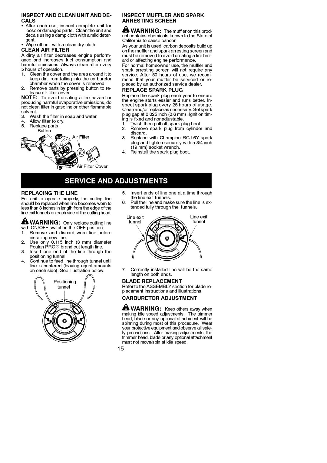
Button
Air Filter
Air Filter Cover
INSPECT MUFFLER AND SPARK ARRESTING SCREEN
![]() WARNING: The muffler on this prod- uct contains chemicals known to the State of California to cause cancer.
WARNING: The muffler on this prod- uct contains chemicals known to the State of California to cause cancer.
As your unit is used, carbon deposits build up on the muffler and spark arresting screen and must be removed to avoid creating a fire haz- ard or affecting engine performance.
For normal homeowner use, the muffler and spark arresting screen will not require any service. After 50 hours of use, we recom- mend that your muffler be serviced or re- placed by an authorized service dealer.
REPLACE SPARK PLUG
Replace the spark plug each year to ensure the engine starts easier and runs better. In- spect spark plug every 25 hours of usage. Clean and/or replace as necessary. Set spark plug gap at 0.025 inch (0.6 mm). Ignition tim- ing is fixed and nonadjustable.
1.Twist, then pull off spark plug boot.
2.Remove spark plug from cylinder and discard.
3.Replace with Champion
4.Reinstall the spark plug boot.
SERVICE AND ADJUSTMENTS
REPLACING THE LINE
For unit to operate properly, the cutting line should be replaced when line becomes worn to less than 3 inches in length from the edge of the line exit tunnels on each side of the cutting head.
![]() WARNING: Only replace cutting line with ON/OFF switch in the OFF position.
WARNING: Only replace cutting line with ON/OFF switch in the OFF position.
1.Remove and discard worn line before installing new line.
2.Use only 0.115 inch (3 mm) diameter Poulan PROR brand cut length line.
3.Insert one end of the line through the positioning tunnel.
4.Continue to feed line through tunnel until line is centered (leaving equal amounts on each side). See illustration below.
Positioning tunnel
5.Insert ends of line one at a time through the line exit tunnels.
6.Pull the line and make sure the line is ex- tended fully through the tunnels.
Line exit | Line exit |
tunnel | tunnel |
7.Correctly installed line will be the same length on both ends.
BLADE REPLACEMENT
Refer to the ASSEMBLY section for blade re- placement instructions and illustrations.
CARBURETOR ADJUSTMENT
![]() WARNING: Keep others away when making idle speed adjustments. The trimmer head, blade or any optional attachment will be spinning during most of this procedure. Wear your protective equipment and observe all safe- ty precautions. After making adjustments, the trimmer head, blade or any optional attachment must not move/spin at idle speed.
WARNING: Keep others away when making idle speed adjustments. The trimmer head, blade or any optional attachment will be spinning during most of this procedure. Wear your protective equipment and observe all safe- ty precautions. After making adjustments, the trimmer head, blade or any optional attachment must not move/spin at idle speed.
15