COM128 specifications
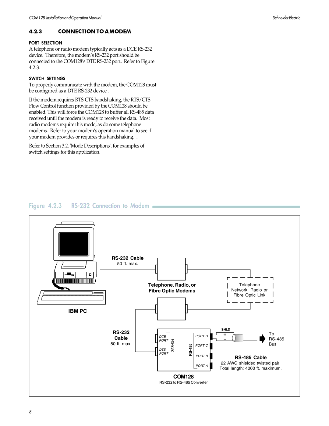
The PowerLogix COM128 is an advanced, high-performance communication module designed to facilitate robust and efficient data exchange in various applications. It is particularly favored in sectors such as industrial automation, smart grid systems, and telecommunication networks.One of the main features of the COM128 module is its flexibility in communication protocols. It supports various standards including Modbus, CAN, and Ethernet/IP, which enables seamless integration into different systems. This adaptability is crucial for industries that employ diverse equipment and protocols, allowing the COM128 to serve as a single communication interface.
The COM128 also boasts impressive data transmission speeds, typically reaching up to 115.2 kbps, ensuring that even large volumes of data can be exchanged quickly and reliably. This is essential in environments where real-time data processing and timely decision-making are critical. The module is capable of handling multiple simultaneous connections, enhancing its efficiency and throughput.
In terms of technology, the COM128 is built on a compact and robust architecture that guarantees durability and longevity. It features advanced error detection and correction mechanisms, which help maintain data integrity during transmission. Additionally, the module is equipped with an integrated power management system that optimizes energy consumption, making it an eco-friendly choice for businesses looking to reduce their carbon footprint.
The characteristics of the PowerLogix COM128 further enhance its appeal. It is designed to operate in a wide range of environmental conditions, with an operational temperature range from -40°C to +85°C. This makes it ideal for deployment in harsh industrial settings where extreme temperatures can be a concern. Furthermore, the module is compact and lightweight, allowing for easy installation and integration into existing systems without the need for significant modifications.
A user-friendly interface accompanies the COM128, providing intuitive configuration options and diagnostics tools. This ease of use reduces the learning curve for engineers and technicians, thereby accelerating project implementation times.
In summary, the PowerLogix COM128 is a versatile and powerful communication module that meets the needs of various industries. With its multi-protocol support, high data transmission speeds, advanced technologies, and robust characteristics, it stands out as a reliable solution for efficient data communication in modern applications.

