This machine must be grounded. Grounding provides a path of least resistance to help divert current away from the operator in case of electrical malfunction.
Make sure the voltage of your power supply matches the specifications on the motor plate of the machine.
Extension Cords
The use of an extension cord is not recommended for this machine, but if one is necessary make sure the cord rating is suitable for the amperage listed on the machine's motor plate. An undersize cord will cause a drop in line voltage resulting in loss of power and overheating.
The chart in Figure 11 shows the correct size cord to use based on cord length and motor plate amp rating. If in doubt, use the next heavier gauge. The smaller the gauge number the heavier the cord.
Adjustments
Tools required for assembly:
10, 12 and 17mm
0.2” (0.5mm) feeler gauge straight edge
gauge block
![]() Disconnect machine from power source before making any adjustments (except feed rate).
Disconnect machine from power source before making any adjustments (except feed rate).
Belt Tension
Inspect the tension of the belts frequently during the first few times you use the planer. Belts often stretch during this trial period. If they require tightening, proceed as follows:
1.Remove the belt guard and the rear panel.
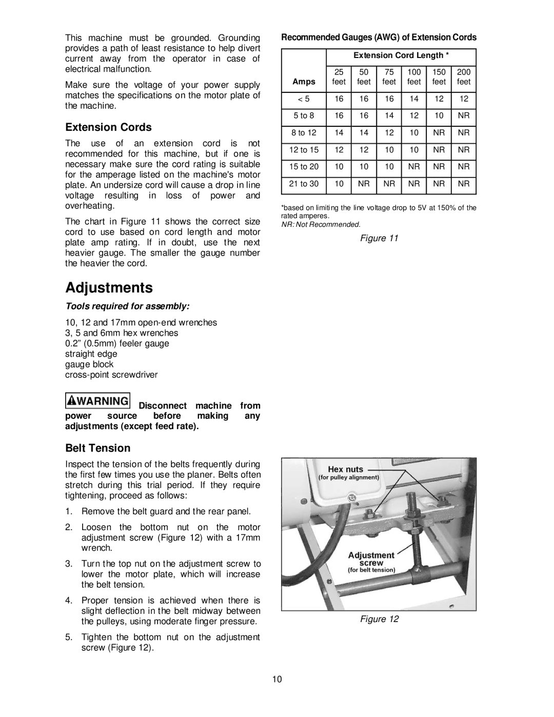
2.Loosen the bottom nut on the motor adjustment screw (Figure 12) with a 17mm wrench.
3.Turn the top nut on the adjustment screw to lower the motor plate, which will increase the belt tension.
4.Proper tension is achieved when there is slight deflection in the belt midway between the pulleys, using moderate finger pressure.
5.Tighten the bottom nut on the adjustment screw (Figure 12).
Recommended Gauges (AWG) of Extension Cords
|
|
| Extension Cord Length * |
| |||
|
|
|
|
|
|
|
|
Amps | 25 | 50 | 75 | 100 | 150 | 200 | |
feet | feet | feet | feet | feet | feet | ||
|
|
|
|
|
|
|
|
< 5 |
| 16 | 16 | 16 | 14 | 12 | 12 |
|
|
|
|
|
|
|
|
5 to | 8 | 16 | 16 | 14 | 12 | 10 | NR |
|
|
|
|
|
|
| |
8 to 12 | 14 | 14 | 12 | 10 | NR | NR | |
|
|
|
|
|
|
|
|
12 to | 15 | 12 | 12 | 10 | 10 | NR | NR |
|
|
|
|
|
|
|
|
15 to | 20 | 10 | 10 | 10 | NR | NR | NR |
|
|
|
|
|
|
|
|
21 to | 30 | 10 | NR | NR | NR | NR | NR |
|
|
|
|
|
|
|
|
*based on limiting the line voltage drop to 5V at 150% of the rated amperes.
NR: Not Recommended.
Figure 11
Figure 12
10
