I V . A S S E M B L Y
INITIAL ASSEMBLY
Your power chair may require some assembly either before initial use or after transportation. It may also require disassembly to make some comfort adjustments.
NOTE: Any nylon insert lock nut removed during the disassembly or adjustment of the power chair must be replaced with a new nut. Nylon insert lock nuts should not be reused as it may cause damage to the nylon insert, resulting in a less secure fit. Replacement nylon insert lock nuts are available at local hardware stores or through your authorized Pride Provider.
Seat Installation
It may be necessary to install the seat either prior to initial operation or after transporting your power chair. Most seats are attached to the power base with the Universal Mounting System (UMS). The UMS consists of universal parts that may be attached to any
WARNING! Do not pick up the seat frame by the armrests. They are free to pivot, and you may lose control of the seat if they do so, resulting in personal injury or damage to the chair.
To install the seat:
1.Set the trapeze bars to the desired height. To change the trapeze bar height, see VI. “Comfort Adjustments.”
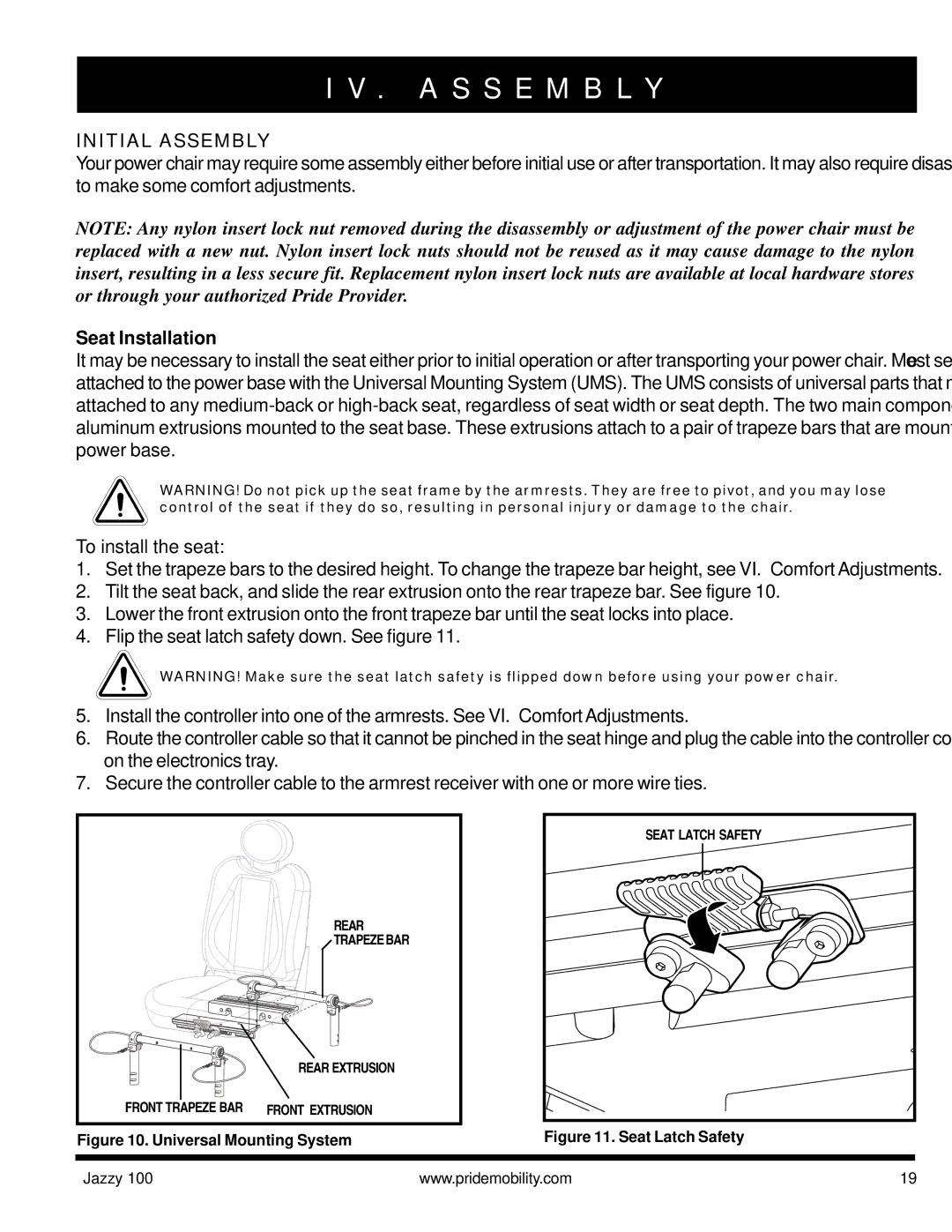
2.Tilt the seat back, and slide the rear extrusion onto the rear trapeze bar. See figure 10.
3.Lower the front extrusion onto the front trapeze bar until the seat locks into place.
4.Flip the seat latch safety down. See figure 11.
![]() WARNING! Make sure the seat latch safety is flipped down before using your power chair.
WARNING! Make sure the seat latch safety is flipped down before using your power chair.
5.Install the controller into one of the armrests. See VI. “Comfort Adjustments.”
6.Route the controller cable so that it cannot be pinched in the seat hinge and plug the cable into the controller connector on the electronics tray.
7.Secure the controller cable to the armrest receiver with one or more wire ties.
| REAR |
| TRAPEZE BAR |
| REAR EXTRUSION |
FRONT TRAPEZE BAR | FRONT EXTRUSION |
Figure 10. Universal Mounting System
SEAT LATCH SAFETY |
Figure 11. Seat Latch Safety
Jazzy 100 | www.pridemobility.com | 19 |