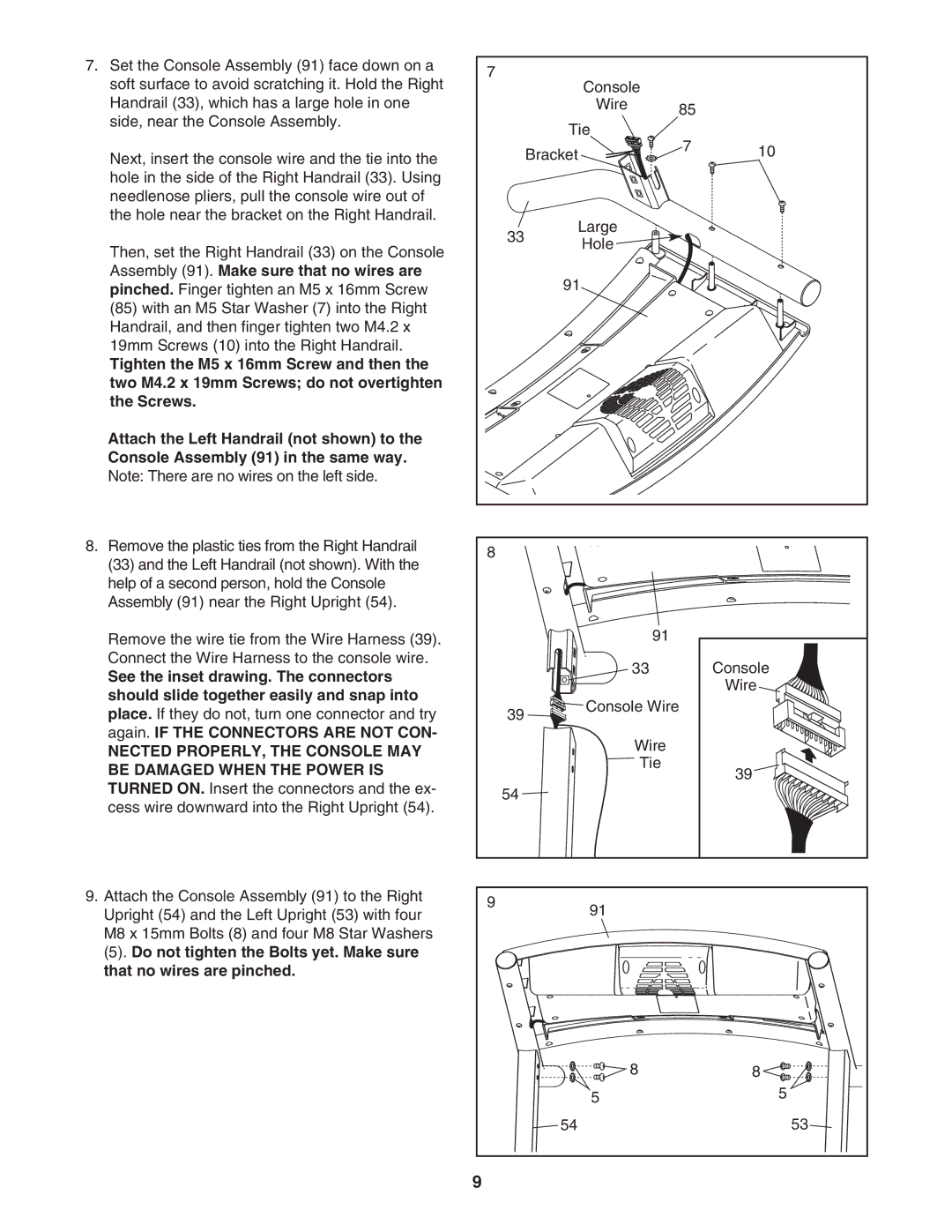
7. Set the Console Assembly (91) face down on a | 7 |
|
|
|
|
soft surface to avoid scratching it. Hold the Right |
| Console |
|
| |
|
|
|
| ||
Handrail (33), which has a large hole in one |
|
| Wire | 85 |
|
side, near the Console Assembly. |
|
|
|
| |
|
| Tie |
|
| |
|
|
| 7 |
| |
Next, insert the console wire and the tie into the |
|
| Bracket | 10 | |
|
|
| |||
hole in the side of the Right Handrail (33). Using |
|
|
|
|
|
needlenose pliers, pull the console wire out of |
|
|
|
|
|
the hole near the bracket on the Right Handrail. |
|
| Large |
|
|
|
| 33 |
|
| |
Then, set the Right Handrail (33) on the Console |
| Hole |
|
| |
|
|
|
| ||
|
|
|
|
| |
Assembly (91). Make sure that no wires are |
|
| 91 |
|
|
pinched. Finger tighten an M5 x 16mm Screw |
|
|
|
| |
(85) with an M5 Star Washer (7) into the Right |
|
|
|
|
|
Handrail, and then finger tighten two M4.2 x |
|
|
|
|
|
19mm Screws (10) into the Right Handrail. |
|
|
|
|
|
Tighten the M5 x 16mm Screw and then the |
|
|
|
|
|
two M4.2 x 19mm Screws; do not overtighten |
|
|
|
|
|
the Screws. |
|
|
|
|
|
Attach the Left Handrail (not shown) to the |
|
|
|
|
|
Console Assembly (91) in the same way. |
|
|
|
|
|
Note: There are no wires on the left side. |
|
|
|
|
|
8. Remove the plastic ties from the Right Handrail | 8 |
|
|
|
|
(33) and the Left Handrail (not shown). With the |
|
|
|
| |
|
|
|
|
| |
help of a second person, hold the Console |
|
|
|
|
|
Assembly (91) near the Right Upright (54). |
|
|
|
|
|
Remove the wire tie from the Wire Harness (39). |
|
| 91 |
|
|
Connect the Wire Harness to the console wire. |
|
| 33 |
| Console |
See the inset drawing. The connectors |
|
|
| ||
|
|
|
| Wire | |
should slide together easily and snap into |
|
|
|
| |
|
| Console Wire |
| ||
place. If they do not, turn one connector and try |
| 39 |
| ||
|
|
|
| ||
again. IF THE CONNECTORS ARE NOT CON- |
|
| Wire |
|
|
NECTED PROPERLY, THE CONSOLE MAY |
|
|
|
| |
|
| Tie |
|
| |
BE DAMAGED WHEN THE POWER IS |
|
|
| 39 | |
|
|
|
| ||
TURNED ON. Insert the connectors and the ex- |
| 54 |
|
|
|
cess wire downward into the Right Upright (54). |
|
|
|
| |
|
|
|
|
| |
9. Attach the Console Assembly (91) to the Right | 9 |
| 91 |
|
|
Upright (54) and the Left Upright (53) with four |
|
|
| ||
|
|
|
| ||
M8 x 15mm Bolts (8) and four M8 Star Washers |
|
|
|
|
|
(5). Do not tighten the Bolts yet. Make sure |
|
|
|
|
|
that no wires are pinched. |
|
|
|
|
|
|
|
| 8 |
| 8 |
|
|
| 5 |
| 5 |
|
|
| 54 |
| 53 |
| 9 |
|
|
|
|
