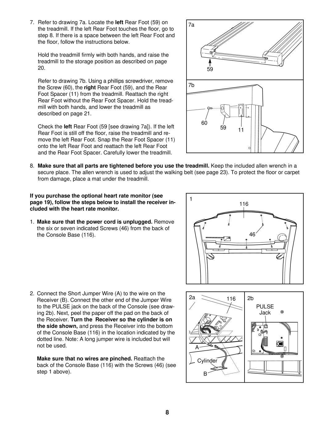
7.Refer to drawing 7a. Locate the left Rear Foot (59) on the treadmill. If the left Rear Foot touches the floor, go to step 8. If there is a space between the left Rear Foot and the floor, follow the instructions below.
Hold the treadmill firmly with both hands, and raise the treadmill to the storage position as described on page 20.
Refer to drawing 7b. Using a phillips screwdriver, remove the Screw (60), the right Rear Foot (59), and the Rear Foot Spacer (11) from the treadmill. Reattach the right Rear Foot without the Rear Foot Spacer. Hold the tread- mill with both hands, and lower the treadmill as described on page 21.
Check the left Rear Foot (59 [see drawing 7a]). If the left Rear Foot is still off the floor, raise the treadmill and re- move the left Rear Foot. Snap the Rear Foot Spacer (11) onto the left Rear Foot and reattach the left Rear Foot and the Rear Foot Spacer. Carefully lower the treadmill.
7a |
|
59 |
|
7b |
|
60 |
|
59 | 11 |
|
8.Make sure that all parts are tightened before you use the treadmill. Keep the included allen wrench in a secure place. The allen wrench is used to adjust the walking belt (see page 23). To protect the floor or carpet from damage, place a mat under the treadmill.
If you purchase the optional heart rate monitor (see page 19), follow the steps below to install the receiver in- cluded with the heart rate monitor.
1.Make sure that the power cord is unplugged. Remove the six or seven indicated Screws (46) from the back of the Console Base (116).
2.Connect the Short Jumper Wire (A) to the wire on the Receiver (B). Connect the other end of the Jumper Wire to the PULSE jack on the back of the Console (see draw- ing 2b). Next, peel the paper off the pad on the back of the Receiver. Turn the Receiver so the cylinder is on the side shown, and press the Receiver into the bottom of the Console Base (116) in the location indicated by the dotted line. Note: A long jumper wire is included but will not be used.
Make sure that no wires are pinched. Reattach the back of the Console Base (116) with the Screws (46) (see step 1 above).
1 |
| 116 |
|
| |
|
| 46 |
2a | 116 | 2b |
|
| PULSE |
|
| Jack |
| A |
|
| Cylinder |
|
| B |
|
8
