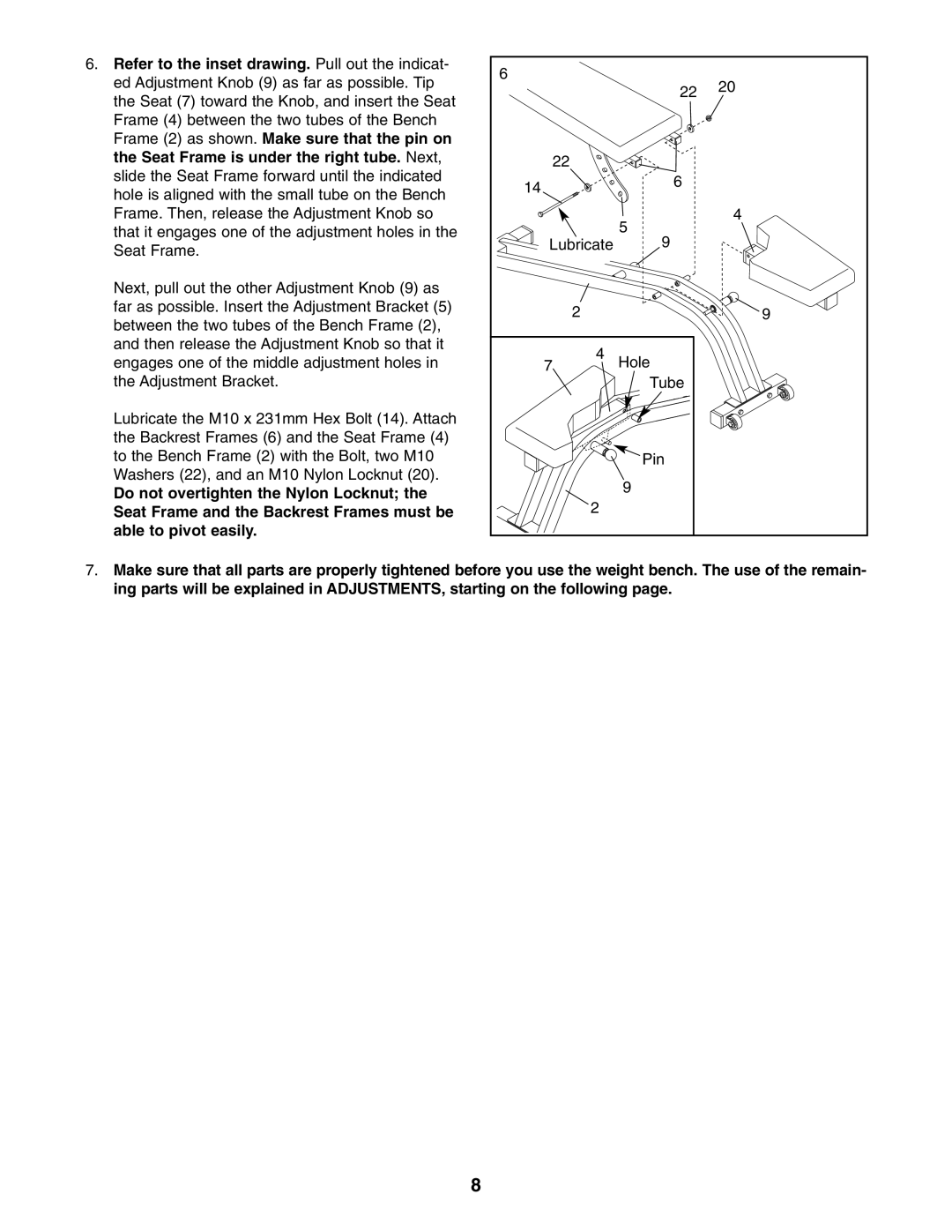
6. Refer to the inset drawing. Pull out the indicat- | 6 |
|
|
|
ed Adjustment Knob (9) as far as possible. Tip |
|
| 20 | |
|
| 22 | ||
the Seat (7) toward the Knob, and insert the Seat |
|
|
| |
|
|
|
| |
Frame (4) between the two tubes of the Bench |
|
|
|
|
Frame (2) as shown. Make sure that the pin on |
|
|
|
|
the Seat Frame is under the right tube. Next, |
| 22 |
|
|
slide the Seat Frame forward until the indicated | 14 |
| 6 |
|
hole is aligned with the small tube on the Bench |
|
| ||
|
|
| ||
|
|
|
| |
Frame. Then, release the Adjustment Knob so |
|
| 5 | 4 |
that it engages one of the adjustment holes in the |
|
|
| |
Lubricate | 9 |
| ||
Seat Frame. |
| |||
|
|
|
| |
Next, pull out the other Adjustment Knob (9) as |
|
|
|
|
far as possible. Insert the Adjustment Bracket (5) |
| 2 |
| 9 |
between the two tubes of the Bench Frame (2), |
|
| ||
|
|
|
| |
and then release the Adjustment Knob so that it |
| 4 |
|
|
engages one of the middle adjustment holes in | 7 | Hole |
| |
the Adjustment Bracket. |
|
| Tube |
|
Lubricate the M10 x 231mm Hex Bolt (14). Attach |
|
|
|
|
the Backrest Frames (6) and the Seat Frame (4) |
|
|
|
|
to the Bench Frame (2) with the Bolt, two M10 |
|
| Pin |
|
Washers (22), and an M10 Nylon Locknut (20). |
|
| 9 |
|
Do not overtighten the Nylon Locknut; the |
|
|
| |
| 2 |
|
| |
Seat Frame and the Backrest Frames must be |
|
|
| |
able to pivot easily. |
|
|
|
|
7.Make sure that all parts are properly tightened before you use the weight bench. The use of the remain- ing parts will be explained in ADJUSTMENTS, starting on the following page.
8