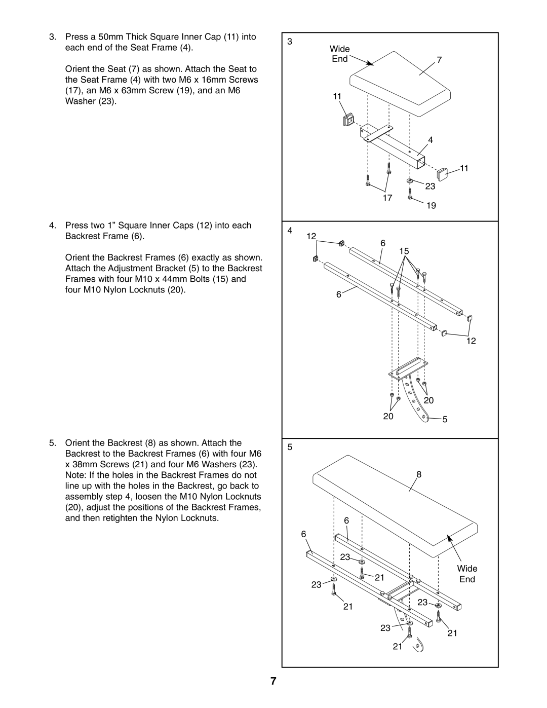
3.Press a 50mm Thick Square Inner Cap (11) into each end of the Seat Frame (4).
Orient the Seat (7) as shown. Attach the Seat to the Seat Frame (4) with two M6 x 16mm Screws (17), an M6 x 63mm Screw (19), and an M6 Washer (23).
4.Press two 1” Square Inner Caps (12) into each Backrest Frame (6).
Orient the Backrest Frames (6) exactly as shown. Attach the Adjustment Bracket (5) to the Backrest Frames with four M10 x 44mm Bolts (15) and four M10 Nylon Locknuts (20).
5.Orient the Backrest (8) as shown. Attach the Backrest to the Backrest Frames (6) with four M6 x 38mm Screws (21) and four M6 Washers (23). Note: If the holes in the Backrest Frames do not line up with the holes in the Backrest, go back to assembly step 4, loosen the M10 Nylon Locknuts (20), adjust the positions of the Backrest Frames, and then retighten the Nylon Locknuts.
7
3 |
|
Wide |
|
End | 7 |
11 |
|
| 4 |
| 11 |
| 23 |
17 | 19 |
| |
4 |
|
12 |
|
6 |
|
15 |
|
6 |
|
| 12 |
| 20 |
20 | 5 |
| |
5 |
|
| 8 |
6 |
|
6 |
|
23 |
|
21 | Wide |
End | |
23 |
|
21 | 23 |
| |
23 | 21 |
| |
21 |
|