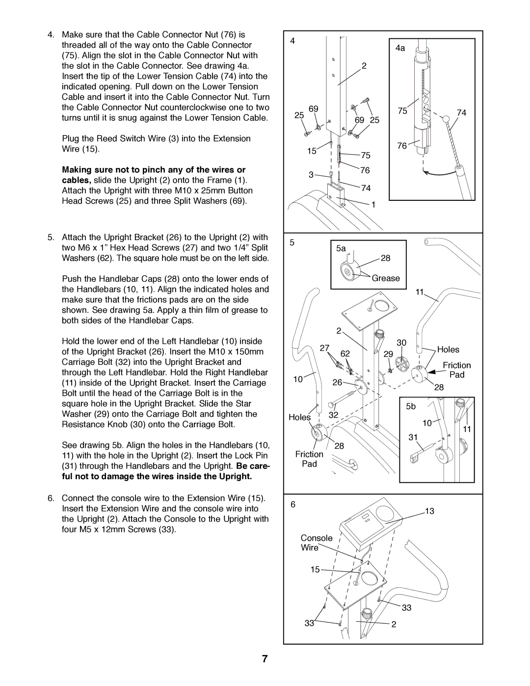
4.Make sure that the Cable Connector Nut (76) is threaded all of the way onto the Cable Connector
(75). Align the slot in the Cable Connector Nut with the slot in the Cable Connector. See drawing 4a. Insert the tip of the Lower Tension Cable (74) into the indicated opening. Pull down on the Lower Tension Cable and insert it into the Cable Connector Nut. Turn the Cable Connector Nut counterclockwise one to two turns until it is snug against the Lower Tension Cable.
Plug the Reed Switch Wire (3) into the Extension Wire (15).
Making sure not to pinch any of the wires or cables, slide the Upright (2) onto the Frame (1). Attach the Upright with three M10 x 25mm Button Head Screws (25) and three Split Washers (69).
5.Attach the Upright Bracket (26) to the Upright (2) with two M6 x 1Ó Hex Head Screws (27) and two 1/4Ó Split Washers (62). The square hole must be on the left side.
Push the Handlebar Caps (28) onto the lower ends of the Handlebars (10, 11). Align the indicated holes and make sure that the frictions pads are on the side shown. See drawing 5a. Apply a thin film of grease to both sides of the Handlebar Caps.
Hold the lower end of the Left Handlebar (10) inside of the Upright Bracket (26). Insert the M10 x 150mm Carriage Bolt (32) into the Upright Bracket and through the Left Handlebar. Hold the Right Handlebar
(11)inside of the Upright Bracket. Insert the Carriage Bolt until the head of the Carriage Bolt is in the square hole in the Upright Bracket. Slide the Star Washer (29) onto the Carriage Bolt and tighten the Resistance Knob (30) onto the Carriage Bolt.
See drawing 5b. Align the holes in the Handlebars (10,
11) with the hole in the Upright (2). Insert the Lock Pin (31) through the Handlebars and the Upright. Be care- ful not to damage the wires inside the Upright.
6.Connect the console wire to the Extension Wire (15). Insert the Extension Wire and the console wire into the Upright (2). Attach the Console to the Upright with four M5 x 12mm Screws (33).
7
4 |
| 4a |
| |
|
|
| ||
| 2 |
|
| |
69 |
| 75 | 74 | |
25 | 69 | 25 |
| |
|
| |||
15 |
| 76 |
| |
75 |
| |||
|
| |||
3 | 76 |
|
| |
|
|
| ||
| 74 |
| ||
|
| 1 |
| |
5 | 5a |
|
| |
| 28 |
| ||
|
|
| ||
|
| Grease |
| |
|
| 11 | ||
| 2 |
|
| |
27 | 30 | Holes | ||
29 | ||||
| 62 |
| ||
|
|
| Friction | |
10 | 26 |
| Pad | |
| 28 | |||
|
| |||
|
|
| ||
| 32 | 5b |
| |
Holes |
| 10 | ||
|
|
| ||
|
| 31 | 11 | |
| 28 |
| ||
Friction |
|
| ||
|
|
| ||
Pad |
|
|
| |
6 |
|
| 13 | |
|
|
| ||
Console |
|
| ||
Wire |
|
|
| |
15 |
|
|
| |
|
| 33 |
| |
33 |
| 2 |
| |