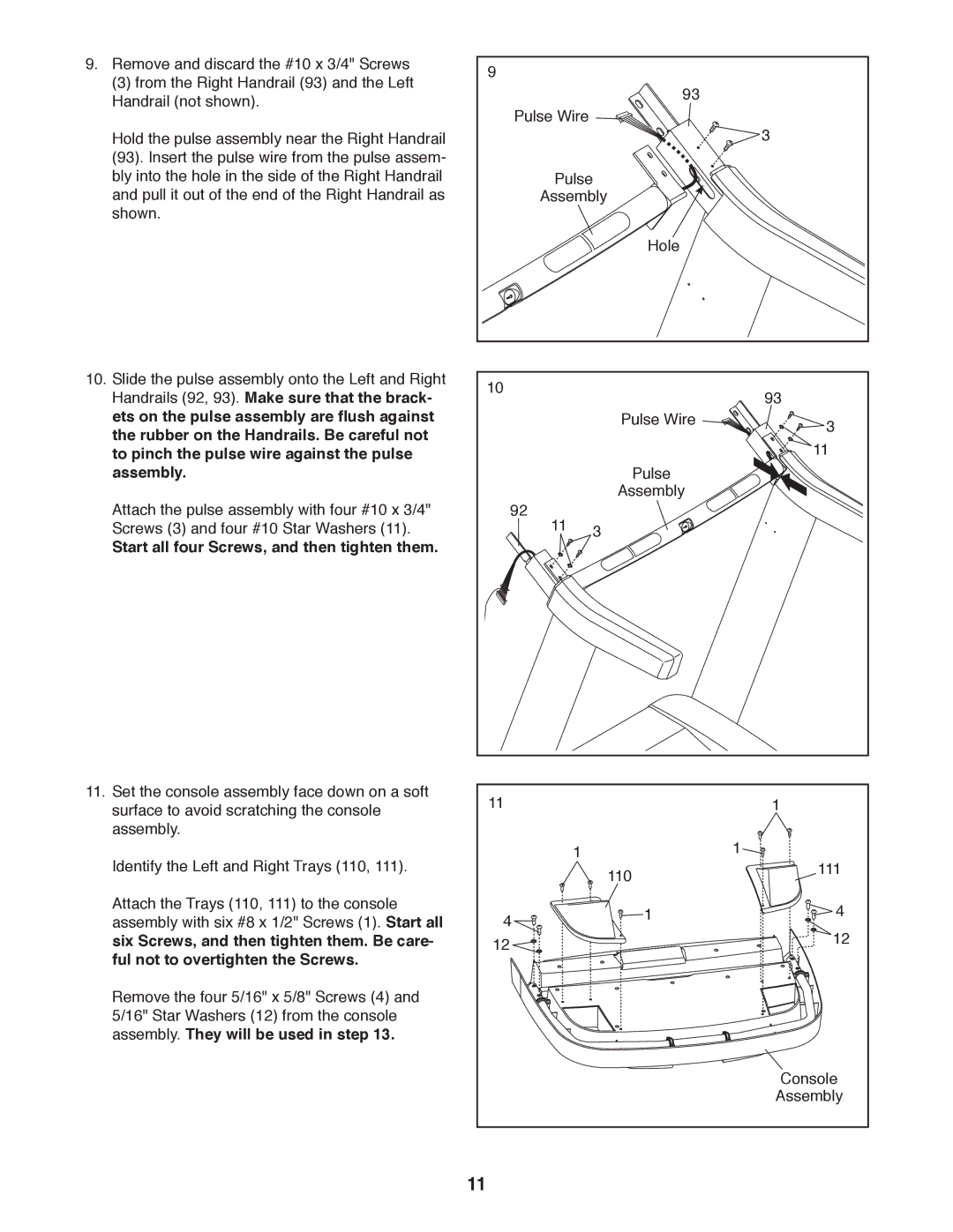
9. | Remove and discard the #10 x 3/4" Screws | 9 |
|
| (3) from the Right Handrail (93) and the Left | 93 | |
|
| ||
| Handrail (not shown). |
| |
|
| Pulse Wire | |
|
|
| |
| Hold the pulse assembly near the Right Handrail |
| 3 |
| (93). Insert the pulse wire from the pulse assem- |
|
|
| bly into the hole in the side of the Right Handrail |
| Pulse |
| and pull it out of the end of the Right Handrail as |
| Assembly |
| shown. |
|
|
|
|
| Hole |
10. | Slide the pulse assembly onto the Left and Right | 10 |
|
| Handrails (92, 93). Make sure that the brack- | 93 | |
|
|
ets on the pulse assembly are flush against |
| Pulse Wire | 3 |
the rubber on the Handrails. Be careful not |
|
| |
|
| 11 | |
to pinch the pulse wire against the pulse |
| Pulse | |
assembly. |
|
| |
Attach the pulse assembly with four #10 x 3/4" | 92 | Assembly |
|
11 3 |
| ||
Screws (3) and four #10 Star Washers (11). |
|
| |
Start all four Screws, and then tighten them. |
|
|
|
11. Set the console assembly face down on a soft | 11 |
| 1 | |
surface to avoid scratching the console |
| |||
assembly. |
| 1 | 1 | |
Identify the Left and Right Trays (110, 111). |
| |||
| 110 | 111 | ||
|
|
| ||
Attach the Trays (110, 111) to the console | 4 | 1 | 4 | |
assembly with six #8 x 1/2" Screws (1). Start all | ||||
| 12 | |||
six Screws, and then tighten them. Be care- | 12 |
| ||
ful not to overtighten the Screws. |
|
|
| |
Remove the four 5/16" x 5/8" Screws (4) and |
|
|
| |
5/16" Star Washers (12) from the console |
|
|
| |
assembly. They will be used in step 13. |
|
|
| |
|
|
| Console | |
|
|
| Assembly | |
| 11 |
|
|