INSTALLATION (2) UA-PRO210
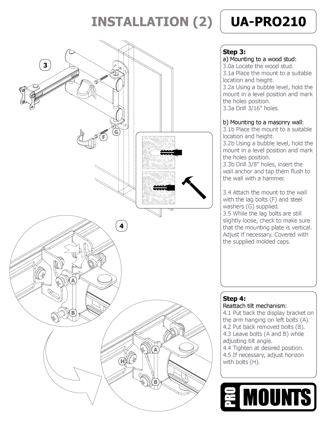
| Step 3: | |
3 | a) Mounting to a wood stud: | |
3.0a Locate the wood stud. | ||
| 3.1a Place the mount to a suitable | |
| location and height. | |
| 3.2a Using a bubble level, hold the | |
| mount in a level position and mark | |
| the holes position. | |
| 3.3a Drill 3/16” holes. | |
| b) Mounting to a masonry wall: | |
G | 3.1b Place the mount to a suitable | |
location and height. | ||
F | ||
| 3.2b Using a bubble level, hold the | |
| mount in a level position and mark | |
| the holes position. | |
| 3.3b Drill 3/8” holes, insert the | |
| wall anchor and tap them flush to | |
| the wall with a hammer. | |
| 3.4 Attach the mount to the wall | |
| with the lag bolts (F) and steel | |
| washers (G) supplied. | |
| 3.5 While the lag bolts are still | |
4 | slightly loose, check to make sure | |
that the mounting plate is vertical. | ||
| Adjust if necessary. Covered with | |
| the supplied molded caps. |
A
Step 4:
| Reattach tilt mechanism: | |
B | 4.1 Put back the display bracket on | |
| the arm hanging on left bolts (A). | |
| 4.2 | Put back removed bolts (B). |
| 4.3 | Leave bolts (A and B) while |
| adjusting tilt angle. | |
A | 4.4 | Tighten at desired position. |
H | 4.5 | If necessary, adjust horizon |
with bolts (H). | ||
B
4
