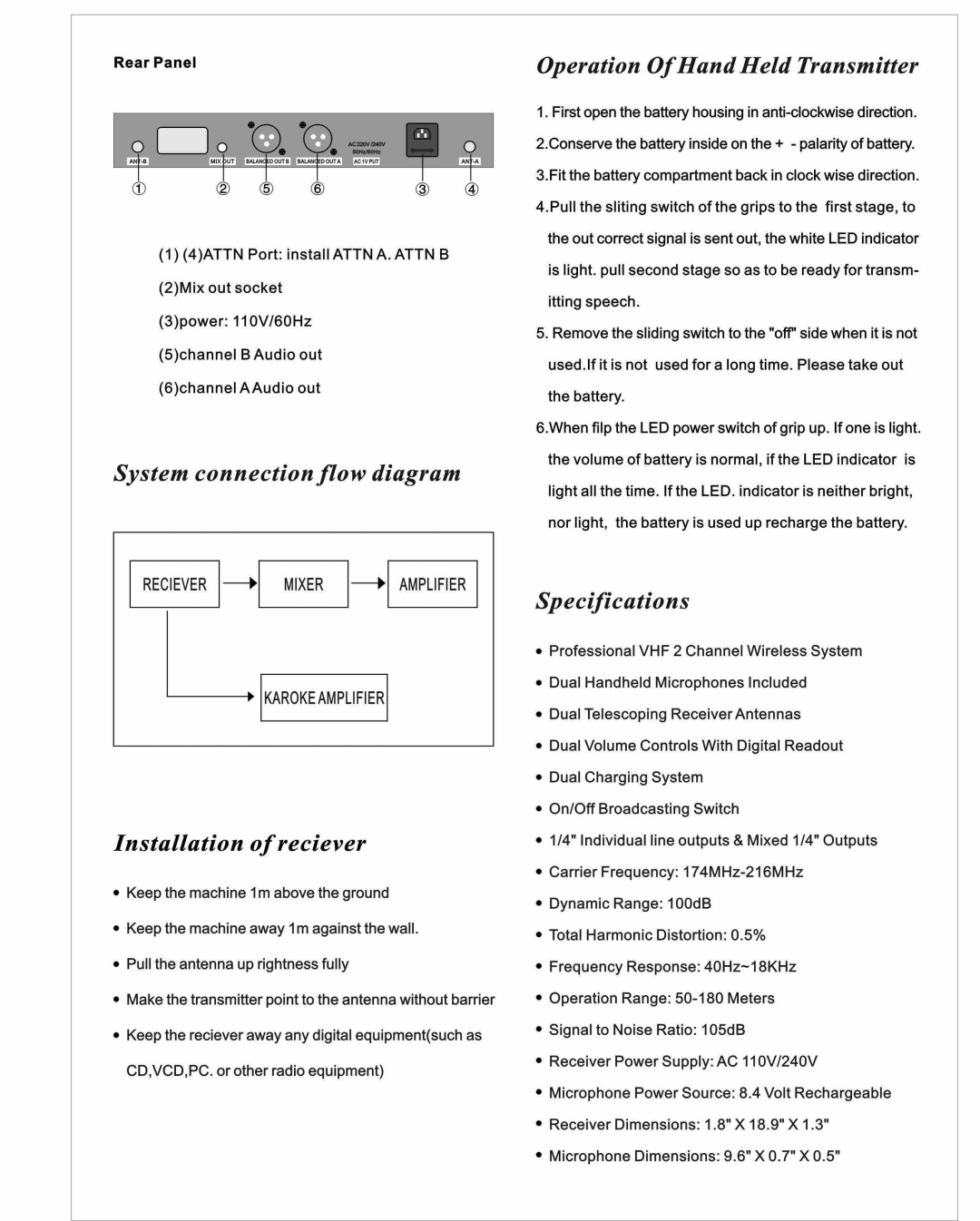
Rear Panel
(1)(4)ATTN Port: install ATTN A. ATTN B (2)Mix out socket
(3)power: 11 OV/60Hz (5)channel B Audio out (6)channel AAudio out
System connection flow diagram
1RECIEVER
L KAROKEAMPLIFIER
Installation ofreciever
•Keep the machine 1m above the ground
•Keep the machine away 1m against the wall.
•Pull the antenna up rightness fully
•Make the transmitter point to the antenna without barrier
•Keep the reciever away any digital equipment(such as CD,VCD,PC. or other radio equipment)
Operation OfHand Held Transmitter
1.First open the battery housing in
itting speech.
5.Remove the sliding switch to the "off'side when it is not used.lf it is not used for a long time. Please take out
the battery.
6.When filp the LED power switch of grip up. If one is light. the volume of battery is normal, if the LED indicator is light all the time. If the LED. indicator is neither bright, nor light, the battery is used up recharge the battery.
Specifications
•Professional VHF 2 Channel Wireless System
•Dual Handheld Microphones Included
•Dual Telescoping Receiver Antennas
•Dual Volume Controls With Digital Readout
•Dual Charging System
•On/Off Broadcasting Switch
•1/4" Individual line outputs & Mixed 1/4" Outputs
•Carrier Frequency:
•Dynamic Range: 100dB
•Total Harmonic Distortion: 0.5%
•Frequency Response:
•Operation Range:
•Signal to Noise Ratio: 105dB
•Receiver Power Supply: AC 11 OV/240V
•Microphone Power Source: 8.4 Volt Rechargeable
•Receiver Dimensions: 1.8" X 18.9" X 1.3"
•Microphone Dimensions: 9.6" X 0.7" X 0.5"