CONFIGURING THE ACCESSORIES
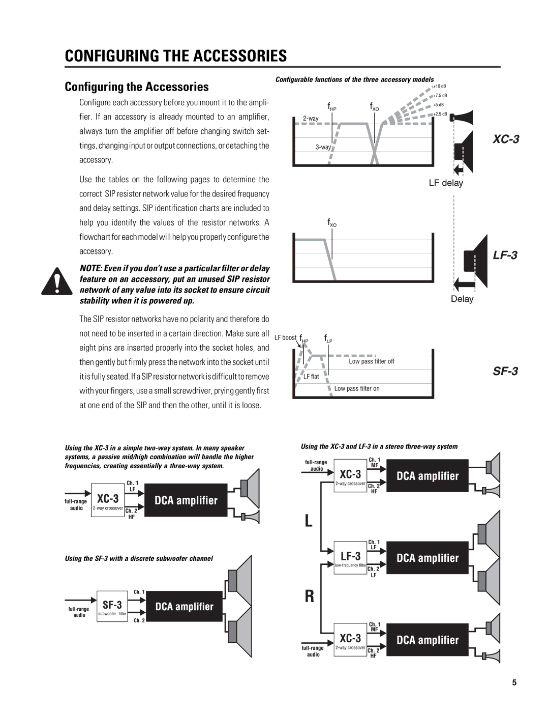
Configurable functions of the three accessory models
Configuring the Accessories
Configure each accessory before you mount it to the ampli- fier. If an accessory is already mounted to an amplifier, always turn the amplifier off before changing switch set- tings, changing input or output connections, or detaching the accessory.
Use the tables on the following pages to determine the correct SIP resistor network value for the desired frequency and delay settings. SIP identification charts are included to help you identify the values of the resistor networks. A flowchart for each model will help you properly configure the accessory.
NOTE: Even if you don’t use a particular filter or delay feature on an accessory, put an unused SIP resistor network of any value into its socket to ensure circuit stability when it is powered up.
The SIP resistor networks have no polarity and therefore do not need to be inserted in a certain direction. Make sure all eight pins are inserted properly into the socket holes, and then gently but firmly press the network into the socket until it is fully seated. If a SIP resistor network is difficult to remove with your fingers, use a small screwdriver, prying gently first at one end of the SIP and then the other, until it is loose.
Using the | Using the | |||||||||||||||||
systems, a passive mid/high combination will handle the higher |
|
|
|
|
|
|
|
| ||||||||||
frequencies, creating essentially a |
|
|
|
|
|
|
|
| ||||||||||
|
|
|
|
|
|
|
| |||||||||||
|
|
|
|
|
|
|
|
|
|
|
|
|
|
|
|
|
|
|
|
|
|
|
|
|
|
|
|
|
|
|
|
|
|
|
|
|
|
|
|
|
|
|
|
|
|
|
|
|
|
|
|
|
|
|
|
|
|
|
|
|
|
|
|
|
|
|
|
|
|
|
|
|
|
|
|
|
|
|
|
|
|
|
|
|
|
|
|
|
|
|
|
|
|
|
|
|
|
|
|
|
|
|
|
|
|
|
|
|
|
|
|
|
|
|
|
|
|
|
|
|
|
|
|
|
|
|
|
|
|
|
|
|
|
|
|
|
|
|
|
|
|
|
|
|
|
|
|
|
|
|
|
|
|
|
|
|
|
|
|
|
|
|
|
|
|
|
|
|
|
|
Using the
5
