7.Place the new driver in the enclosure opening and align its mounting holes with those in the enclosure. With their lockwashers in place, insert the mounting screws and thread them in until they are almost tight.
8.If a
9.
Table 2. Mounting screw torque.
Amount | Units |
|
|
|
|
N•m | |
|
|
|
|
1![]()
![]() 3
3
4![]()
![]() 2
2
Figure 2. Tightening sequences for 12”
driver.
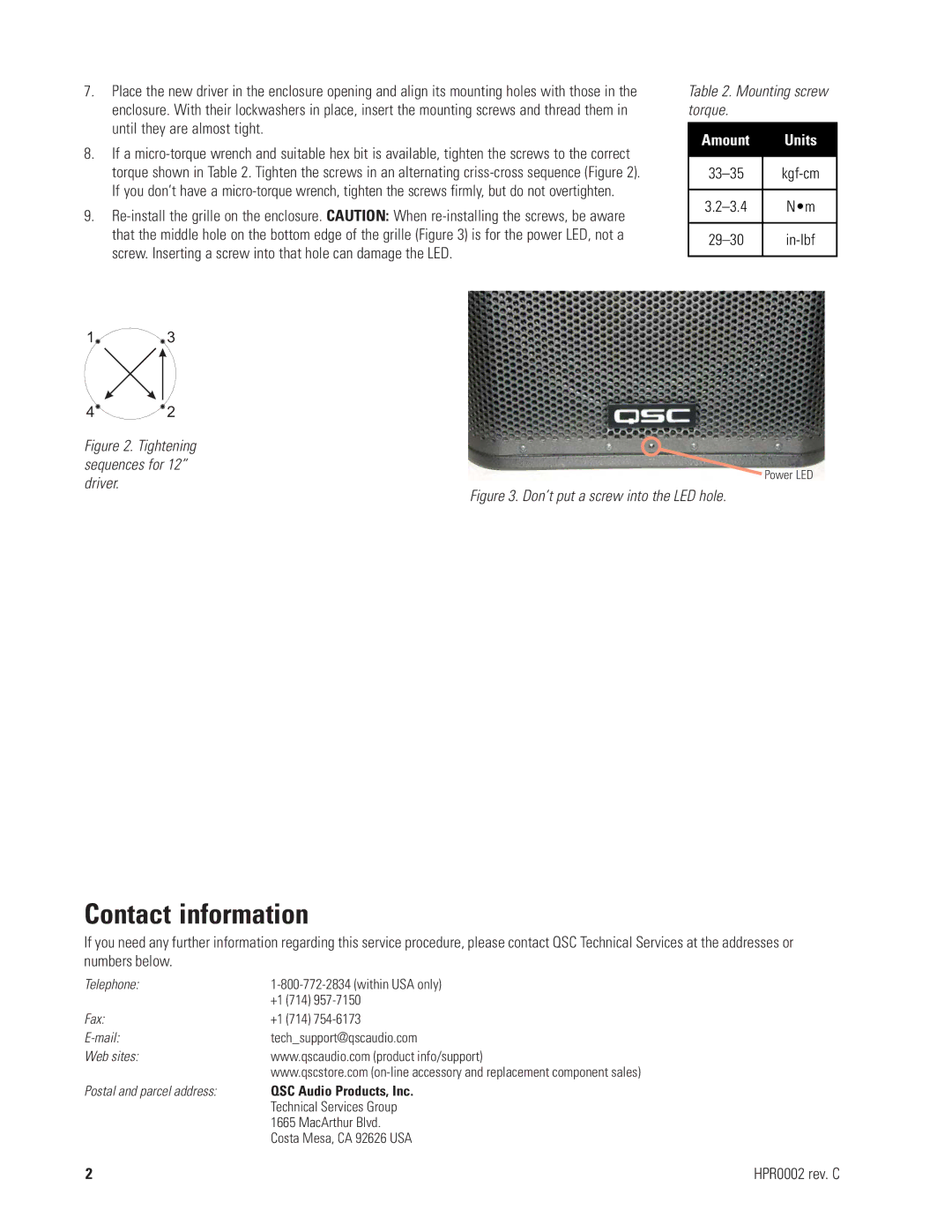
Power LED
Figure 3. Don’t put a screw into the LED hole.
Contact information
If you need any further information regarding this service procedure, please contact QSC Technical Services at the addresses or numbers below.
Telephone: | |
| +1 (714) |
Fax: | +1 (714) |
tech_support@qscaudio.com | |
Web sites: | www.qscaudio.com (product info/support) |
| www.qscstore.com |
Postal and parcel address: | QSC Audio Products, Inc. |
| Technical Services Group |
| 1665 MacArthur Blvd. |
| Costa Mesa, CA 92626 USA |
2 | HPR0002 rev. C |