Input/Output Connections
The MD has a balanced
Balanced connections are recommended for less AC hum and interference, especially with long cable runs. Unbalanced connections may be suitable for short cables. The signal's source impedance should be less than 600 ohms.
Input connection
Insert the male XLR input into the jack marked IN. Ensure the connector is fully seated. The input impedance is 12k ohm balanced or 6k ohm unbalanced.
Balanced inputs: Connect to the plug as shown.
![]() 1= shield (ground)
1= shield (ground)
![]()
![]()
![]()
![]() 3= minus
3= minus ![]()
![]() 2= plus (+)
2= plus (+)
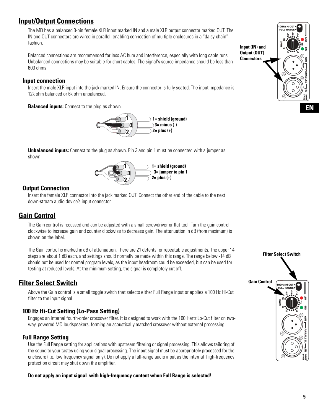
Input (IN) and
Output (OUT)
Connectors
EN
Unbalanced inputs: Connect to the plug as shown. Pin 3 and pin 1 must be connected with a jumper as shown.
1= shield (ground)
![]() 3= jumper to pin 1 2= plus (+)
3= jumper to pin 1 2= plus (+)
Output Connection
Insert the female XLR connector into the jack marked OUT. Connect the other end of the cable to the next
Gain Control
The Gain control is recessed and can be adjusted with a small screwdriver or flat tool. Turn the gain control clockwise to increase gain and counter clockwise to decrease gain. The attenuation in dB (from maximum) is shown on the label.
The Gain control is marked in dB of attenuation. There are 21 detents for repeatable adjustments. The upper 14 steps are about 1 dB each, and settings should normally be made within this range. The range below
Filter Select Switch
Above the Gain control is a small toggle switch that selects either Full Range input or applies a 100 Hz
100 Hz Hi-Cut Setting (Lo-Pass Setting)
Engages an internal
Full Range Setting
Use the Full Range setting for applications with upstream filtering or signal processing. This allows tailoring of the sound to your tastes using your signal processing. The input signal must be appropriately processed for the enclosure (i.e. low frequency signal only). Do not apply a
Do not apply an input signal with
Filter Select Switch
Gain Control
5