Connections
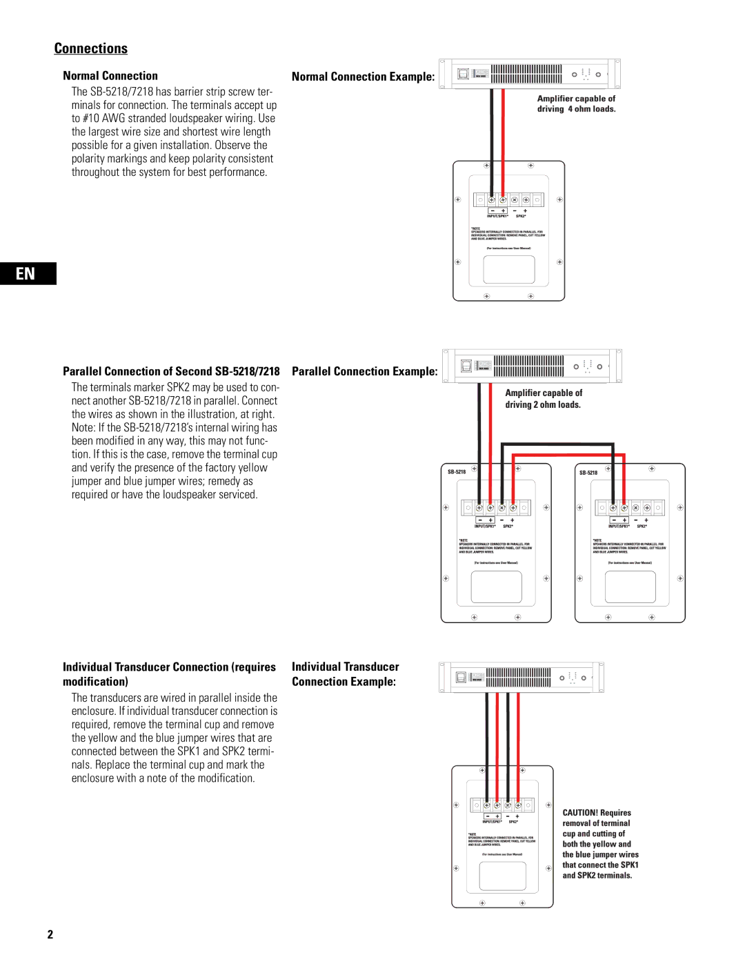
Normal Connection | Normal Connection Example: |
The SB-5218/7218 has barrier strip screw ter- minals for connection. The terminals accept up to #10 AWG stranded loudspeaker wiring. Use the largest wire size and shortest wire length possible for a given installation. Observe the polarity markings and keep polarity consistent throughout the system for best performance.
EN
Parallel Connection of Second SB-5218/7218 Parallel Connection Example:
The terminals marker SPK2 may be used to con- nect another SB-5218/7218 in parallel. Connect the wires as shown in the illustration, at right. Note: If the SB-5218/7218’s internal wiring has been modified in any way, this may not func- tion. If this is the case, remove the terminal cup and verify the presence of the factory yellow jumper and blue jumper wires; remedy as required or have the loudspeaker serviced.
Individual Transducer Connection (requires | Individual Transducer |
modification) | Connection Example: |
The transducers are wired in parallel inside the enclosure. If individual transducer connection is required, remove the terminal cup and remove the yellow and the blue jumper wires that are connected between the SPK1 and SPK2 termi- nals. Replace the terminal cup and mark the enclosure with a note of the modification.