Connections
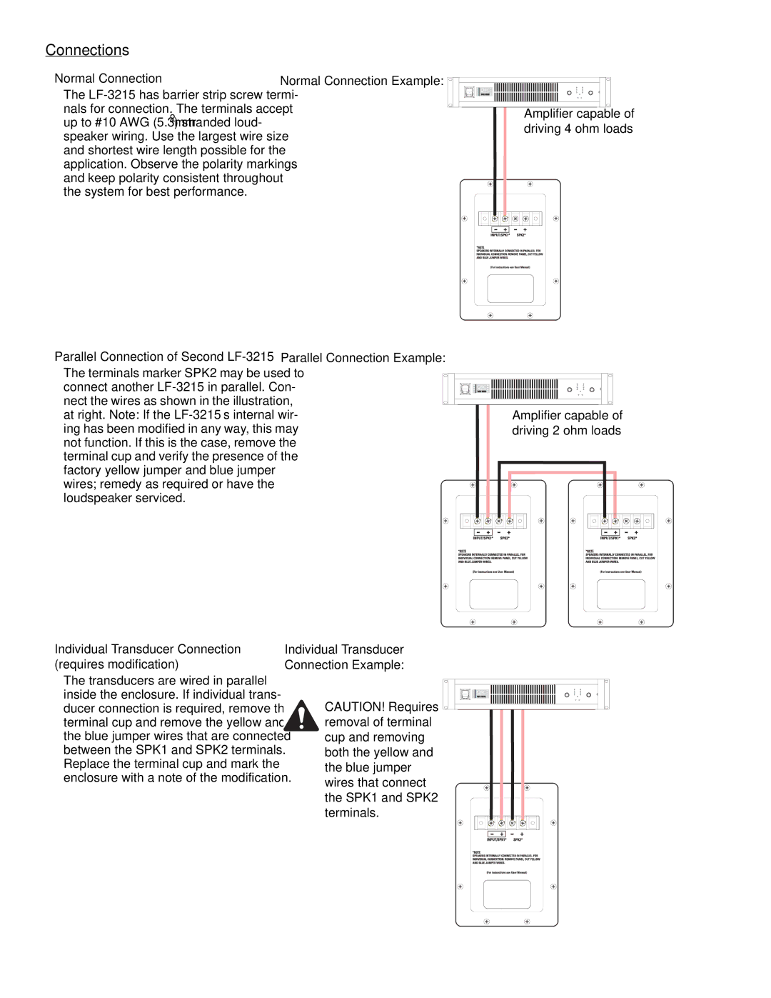
Normal Connection
The
Parallel Connection of Second LF-3215
The terminals marker SPK2 may be used to connect another
Individual Transducer Connection (requires modification)
The transducers are wired in parallel inside the enclosure. If individual trans- ducer connection is required, remove the terminal cup and remove the yellow and the blue jumper wires that are connected between the SPK1 and SPK2 terminals. Replace the terminal cup and mark the enclosure with a note of the modification.
Normal Connection Example:
Amplifier capable of driving 4 ohm loads
Parallel Connection Example:
Amplifier capable of driving 2 ohm loads
Individual Transducer
Connection Example:
CAUTION! Requires removal of terminal cup and removing both the yellow and the blue jumper wires that connect the SPK1 and SPK2 terminals.
