I V . A S S E M B L Y
I V . A S S E M B L Y
INITIAL ASSEMBLY
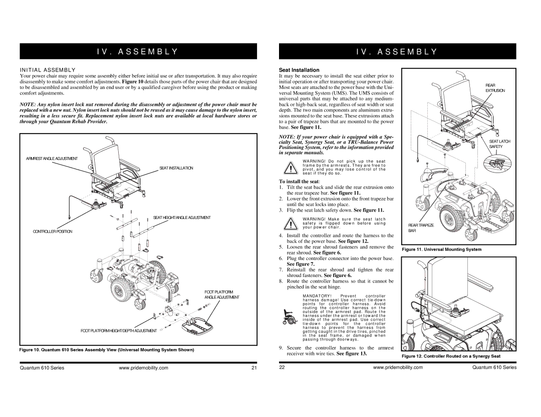
Your power chair may require some assembly either before initial use or after transportation. It may also require disassembly to make some comfort adjustments. Figure 10 details those parts of the power chair that are designed to be disassembled and assembled by an end user or by a qualified caregiver before using the product or making comfort adjustments.
NOTE: Any nylon insert lock nut removed during the disassembly or adjustment of the power chair must be replaced with a new nut. Nylon insert lock nuts should not be reused as it may cause damage to the nylon insert, resulting in a less secure fit. Replacement nylon insert lock nuts are available at local hardware stores or through your Quantum Rehab Provider.
ARMREST ANGLE ADJUSTMENT |
SEAT INSTALLATION |
SEAT HEIGHT/ANGLE ADJUSTMENT |
CONTROLLER POSITION |
FOOT PLATFORM |
ANGLE ADJUSTMENT |
FOOT PLATFORM HEIGHT/DEPTH ADJUSTMENT |
Figure 10. Quantum 610 Series Assembly View (Universal Mounting System Shown)
Seat Installation
It may be necessary to install the seat either prior to initial operation or after transporting your power chair. Most seats are attached to the power base with the Uni- versal Mounting System (UMS). The UMS consists of universal parts that may be attached to any medium- back or
NOTE: If your power chair is equipped with a Spe- cialty Seat, Synergy Seat, or a
WARNING! Do not pick up the seat frame by the armrests. They are free to pivot, and you may lose control of the seat if they do so.
To install the seat:
1. Tilt the seat back and slide the rear extrusion onto the rear trapeze bar. See figure 11.
2. Lower the front extrusion onto the front trapeze bar until the seat locks into place.
3. Flip the seat latch safety down. See figure 11.
WARNING! Make sure the seat latch safety is flipped down before using your power chair.
4.Install the controller and route the harness to the back of the power base. See figure 12.
5.Loosen the rear shroud fasteners and remove the rear shroud. See figure 6.
6.Plug the controller connector into the power base.
See figure 7.
7.Reinstall the rear shroud and tighten the rear shroud fasteners. See figure 6.
8.Route the controller harness so that it cannot be pinched in the seat hinge.
MANDATORY! Prevent controller harness damage! Use correct
9.Secure the controller harness to the armrest receiver with wire ties. See figure 13.
REAR |
EXTRUSION |
SEAT LATCH |
SAFETY |
REAR TRAPEZE |
BAR |
Figure 11. Universal Mounting System
Figure 12. Controller Routed on a Synergy Seat |
Quantum 610 Series | www.pridemobility.com | 21 | 22 | www.pridemobility.com | Quantum 610 Series |