4.4.2 Clock Rate Multiplier
A standard
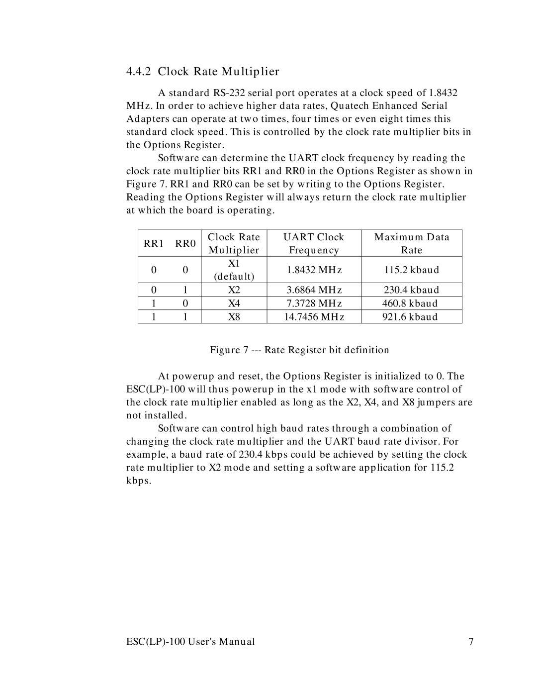
Software can determine the UART clock frequency by reading the clock rate multiplier bits RR1 and RR0 in the Options Register as shown in Figure 7. RR1 and RR0 can be set by writing to the Options Register. Reading the Options Register will always return the clock rate multiplier at which the board is operating.
RR1 | RR0 | Clock Rate | UART Clock | Maximum Data | |
Multiplier | Frequency | Rate | |||
|
| ||||
0 | 0 | X1 | 1.8432 MHz | 115.2 kbaud | |
(default) | |||||
|
|
|
| ||
0 | 1 | X2 | 3.6864 MHz | 230.4 kbaud | |
1 | 0 | X4 | 7.3728 MHz | 460.8 kbaud | |
1 | 1 | X8 | 14.7456 MHz | 921.6 kbaud |
Figure 7 --- Rate Register bit definition
At powerup and reset, the Options Register is initialized to 0. The ESC(LP)-100 will thus powerup in the x1 mode with software control of the clock rate multiplier enabled as long as the X2, X4, and X8 jumpers are not installed.
Software can control high baud rates through a combination of changing the clock rate multiplier and the UART baud rate divisor. For example, a baud rate of 230.4 kbps could be achieved by setting the clock rate multiplier to X2 mode and setting a software application for 115.2 kbps.
7 |