RAD Data comm Main Channel Control Signals, Sub-channel Control Signals, RSD-20/V.35

Models: RSD-20

1 29
Download 29 pages 21.02 Kb
Page 22
Image 22

4.4CONTROL SIGNALS

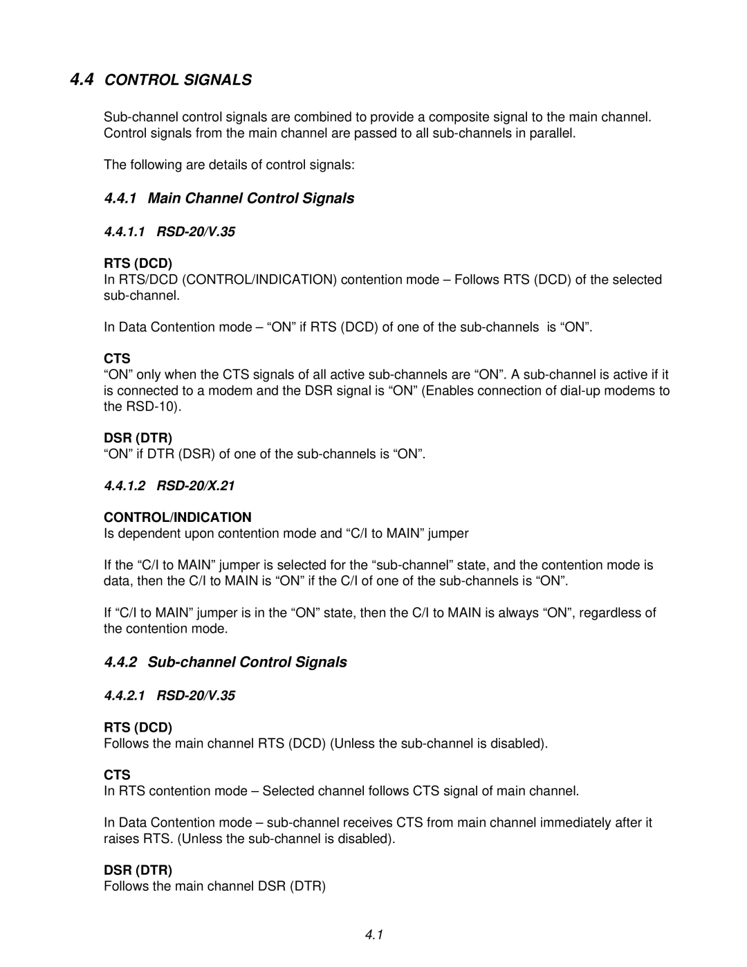
Sub-channel control signals are combined to provide a composite signal to the main channel. Control signals from the main channel are passed to all sub-channels in parallel.

The following are details of control signals:

4.4.1 Main Channel Control Signals

4.4.1.1 RSD-20/V.35

RTS (DCD)

In RTS/DCD (CONTROL/INDICATION) contention mode – Follows RTS (DCD) of the selected sub-channel.

In Data Contention mode – “ON” if RTS (DCD) of one of the sub-channels is “ON”.

CTS

“ON” only when the CTS signals of all active sub-channels are “ON”. A sub-channel is active if it is connected to a modem and the DSR signal is “ON” (Enables connection of dial-up modems to the RSD-10).

DSR (DTR)

“ON” if DTR (DSR) of one of the sub-channels is “ON”.

4.4.1.2 RSD-20/X.21

CONTROL/INDICATION

Is dependent upon contention mode and “C/I to MAIN” jumper

If the “C/I to MAIN” jumper is selected for the “sub-channel” state, and the contention mode is data, then the C/I to MAIN is “ON” if the C/I of one of the sub-channels is “ON”.

If “C/I to MAIN” jumper is in the “ON” state, then the C/I to MAIN is always “ON”, regardless of the contention mode.

4.4.2 Sub-channel Control Signals

4.4.2.1 RSD-20/V.35

RTS (DCD)

Follows the main channel RTS (DCD) (Unless the sub-channel is disabled).

CTS

In RTS contention mode – Selected channel follows CTS signal of main channel.

In Data Contention mode – sub-channel receives CTS from main channel immediately after it raises RTS. (Unless the sub-channel is disabled).

DSR (DTR)

Follows the main channel DSR (DTR)

4.1
Page 22
Image 22
RAD Data comm operation manual Main Channel Control Signals, Sub-channel Control Signals, RSD-20/V.35, RSD-20/X.21