4.Route the adapter and modular cords through the grooves on the bracket.
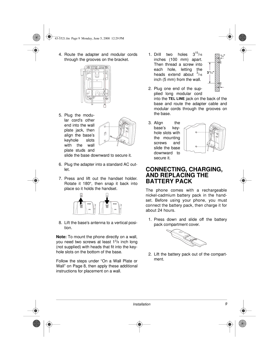
5. Plug the modu-
lar cord's other end into the wall plate jack, then
align the base’s keyhole slots with the wall
plate studs and
slide the base downward to secure it.
6.Plug the adapter into a standard AC out- let.
7.Press and lift out the handset holder. Rotate it 180°, then snap it back into place so it holds the handset.
8.Lift the base's antenna to a vertical posi- tion.
Note: To mount the phone directly on a wall, you need two screws at least 13/8 inch long (not supplied) with heads that fit into the key- hole slots on the bottom of the base.
Follow the steps under “On a Wall Plate or Wall” on Page 8, then apply these additional instructions for placement on a wall.
1. | Drill | two | holes | 315/16 | 3/16" | |
| inches | (100 mm) apart. |
| |||
| Then thread a screw into |
| ||||
| each |
| hole, | letting | the | 315/16" |
| heads | extend about 3/16 | ||||
| inch (5 mm) from the wall. |
| ||||
2. Plug one end of the sup- |
| |||||
| plied | long | modular | cord |
| |
| into the TEL LINE jack on the back of the | |||||
| base and route the adapter cable and | |||||
| modular cords through the grooves on | |||||
| the base. |
|
|
| ||
3. | Align |
| the |
|
| |
| base’s | key- |
|
| ||
| hole slots with |
|
| |||
| the | mounting |
|
| ||
| screws | and |
|
| ||
| slide the base |
|
| |||
| downward | to |
|
| ||
| secure it. |
|
|
| ||
CONNECTING, CHARGING, AND REPLACING THE BATTERY PACK
The phone comes with a rechargeable
1.Press down and slide off the battery pack compartment cover.
2.Lift the battery pack out of the compart- ment.
Installation | 9 |
| ||
|
|
|
|
|
|
|
|
|
|
|
|
|
|
|