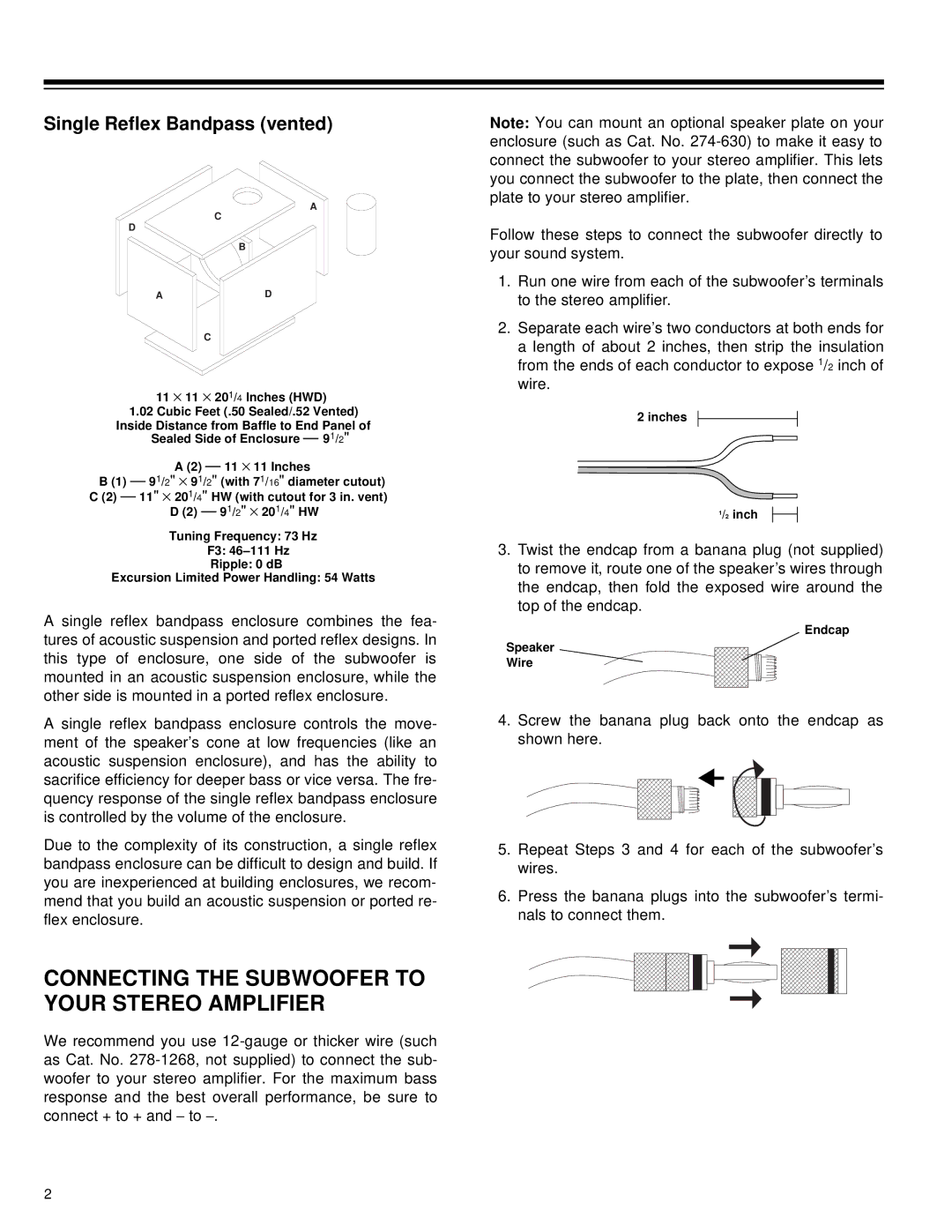
Single Reflex Bandpass (vented)
A
C
D
B
AD
C
11 × 11 × 201/4 Inches (HWD)
1.02Cubic Feet (.50 Sealed/.52 Vented)
Inside Distance from Baffle to End Panel of Sealed Side of Enclosure — 91/2"
A (2) — 11 × 11 Inches
B (1) — 91/2" × 91/2" (with 71/16" diameter cutout)
C (2) — 11" × 201/4" HW (with cutout for 3 in. vent) D (2) — 91/2" × 201/4" HW
Tuning Frequency: 73 Hz
F3:
Ripple: 0 dB
Excursion Limited Power Handling: 54 Watts
A single reflex bandpass enclosure combines the fea- tures of acoustic suspension and ported reflex designs. In this type of enclosure, one side of the subwoofer is mounted in an acoustic suspension enclosure, while the other side is mounted in a ported reflex enclosure.
A single reflex bandpass enclosure controls the move- ment of the speaker’s cone at low frequencies (like an acoustic suspension enclosure), and has the ability to sacrifice efficiency for deeper bass or vice versa. The fre- quency response of the single reflex bandpass enclosure is controlled by the volume of the enclosure.
Due to the complexity of its construction, a single reflex bandpass enclosure can be difficult to design and build. If you are inexperienced at building enclosures, we recom- mend that you build an acoustic suspension or ported re- flex enclosure.
CONNECTING THE SUBWOOFER TO YOUR STEREO AMPLIFIER
We recommend you use
Note: You can mount an optional speaker plate on your enclosure (such as Cat. No.
Follow these steps to connect the subwoofer directly to your sound system.
1.Run one wire from each of the subwoofer’s terminals to the stereo amplifier.
2.Separate each wire’s two conductors at both ends for a length of about 2 inches, then strip the insulation from the ends of each conductor to expose 1/2 inch of wire.
2 inches
1/2 inch
3.Twist the endcap from a banana plug (not supplied) to remove it, route one of the speaker’s wires through the endcap, then fold the exposed wire around the top of the endcap.
![]() Endcap
Endcap
Speaker
Wire
4.Screw the banana plug back onto the endcap as shown here.
5.Repeat Steps 3 and 4 for each of the subwoofer’s wires.
6.Press the banana plugs into the subwoofer’s termi- nals to connect them.
2
