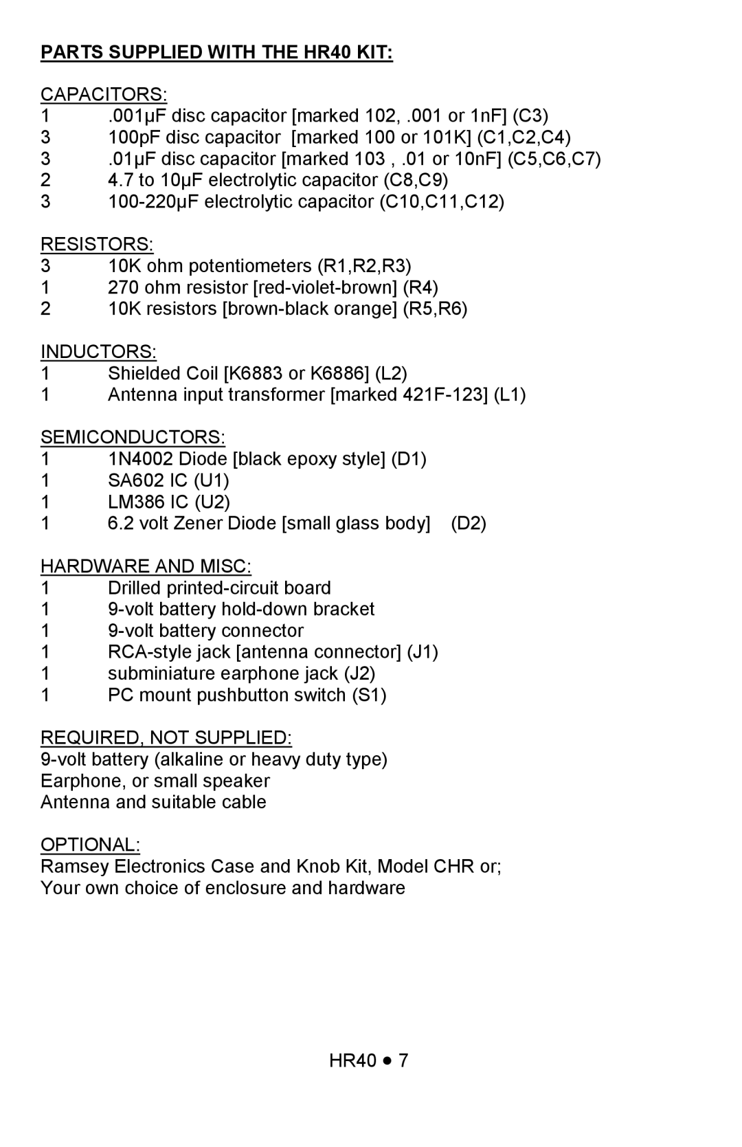
HR40 specifications
The Ramsey Electronics HR40 is a versatile and high-performance FM transmitter that has gained recognition among hobbyists and professionals looking to broadcast audio signals. With its robust features and user-friendly design, the HR40 stands as an excellent choice for a range of applications, from low-power broadcasting to personal audio projects.One of the standout features of the HR40 is its frequency range, typically allowing for transmission on the FM band from 88 to 108 MHz. This broad range ensures compatibility with a variety of receivers and allows users to select an optimal frequency for their needs, minimizing potential interference. The transmitter is designed to offer excellent audio fidelity, with a frequency response that meets and exceeds industry standards, ensuring clear and crisp sound quality.
The HR40 utilizes advanced modulation techniques, which contribute to its performance in terms of signal clarity and range. The use of frequency modulation allows the HR40 to transmit audio signals with minimal distortion, even at higher volume levels. Additionally, the transmitter is equipped with a built-in audio preamplifier, which enhances audio quality by providing a clean and powerful signal before transmission.
Another notable characteristic of the HR40 is its adjustable output power. Users can modify the power level to suit their specific broadcasting needs, whether for indoor use or outdoor applications. This flexibility is particularly useful in managing transmission range, allowing users to tailor their setup without excessive overkill or underperformance.
The compact design of the HR40 also stands out, making it a popular choice for those who need a portable broadcasting solution. The unit is lightweight and easy to transport, while its durable construction ensures longevity and resilience in various environments.
In terms of ease of use, the Ramsey Electronics HR40 offers simple installation and operation. It comes with a clear instruction manual, allowing users to set up their transmitters quickly. The intuitive interface and minimal setup requirements enable beginners to jump right in, while advanced users can take advantage of its expandability and customization options.
Overall, the Ramsey Electronics HR40 combines user-friendliness with a range of powerful features aimed at both amateur and experienced broadcasters. Its excellent audio quality, adjustable output power, and compact design make it a favorite for many seeking reliable FM transmission capabilities.
