‰23. Install R8, a 4.7K ohm resistor (yellow-violet-red).

‰24. Install Q4, a 2N3904 transistor (marked 3904). This transistor is used to amplify the small amount of current provided from the IR detector to a large enough amount to drive the LED indicator. The LED will blink OFF when a signal is seen, so it has a dual use of indicating power as well.

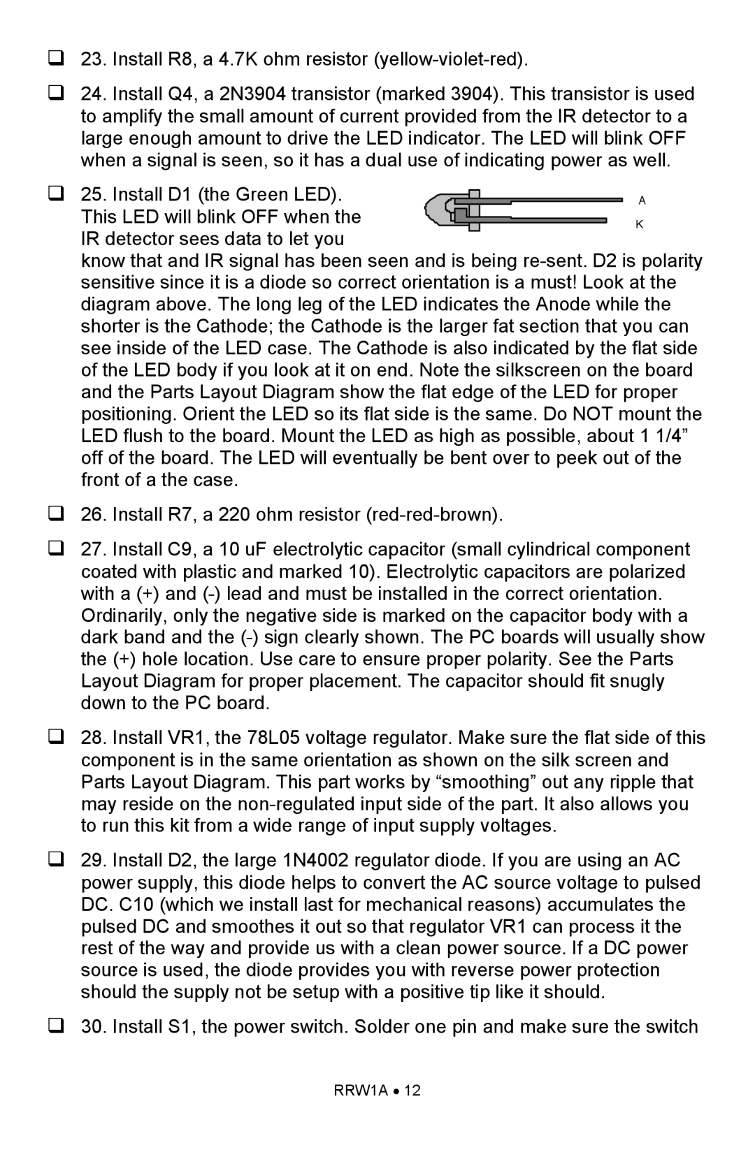
‰ 25. Install D1 (the Green LED).


A


This LED will blink OFF when the


K


IR detector sees data to let you


know that and IR signal has been seen and is being re-sent. D2 is polarity sensitive since it is a diode so correct orientation is a must! Look at the diagram above. The long leg of the LED indicates the Anode while the shorter is the Cathode; the Cathode is the larger fat section that you can see inside of the LED case. The Cathode is also indicated by the flat side of the LED body if you look at it on end. Note the silkscreen on the board and the Parts Layout Diagram show the flat edge of the LED for proper positioning. Orient the LED so its flat side is the same. Do NOT mount the LED flush to the board. Mount the LED as high as possible, about 1 1/4” off of the board. The LED will eventually be bent over to peek out of the front of a the case.

‰26. Install R7, a 220 ohm resistor (red-red-brown).

‰27. Install C9, a 10 uF electrolytic capacitor (small cylindrical component coated with plastic and marked 10). Electrolytic capacitors are polarized with a (+) and (-) lead and must be installed in the correct orientation.

Ordinarily, only the negative side is marked on the capacitor body with a dark band and the (-) sign clearly shown. The PC boards will usually show the (+) hole location. Use care to ensure proper polarity. See the Parts Layout Diagram for proper placement. The capacitor should fit snugly down to the PC board.

‰28. Install VR1, the 78L05 voltage regulator. Make sure the flat side of this component is in the same orientation as shown on the silk screen and Parts Layout Diagram. This part works by “smoothing” out any ripple that may reside on the non-regulated input side of the part. It also allows you to run this kit from a wide range of input supply voltages.

‰29. Install D2, the large 1N4002 regulator diode. If you are using an AC power supply, this diode helps to convert the AC source voltage to pulsed DC. C10 (which we install last for mechanical reasons) accumulates the pulsed DC and smoothes it out so that regulator VR1 can process it the rest of the way and provide us with a clean power source. If a DC power source is used, the diode provides you with reverse power protection should the supply not be setup with a positive tip like it should.

‰30. Install S1, the power switch. Solder one pin and make sure the switch

RRW1A • 12

Page 12
Image 12
Ramsey Electronics RRW1A manual

RRW1A specifications

The Ramsey Electronics RRW1A is a versatile radio frequency (RF) wireless microphone system that stands out due to its robust features and reliable performance. Designed primarily for educational institutions, conferences, and public speaking events, the RRW1A offers a user-friendly experience paired with superior audio quality.

One of the main features of the RRW1A is its RF transmission technology, which allows for seamless communication over distances of up to 300 feet. This range is particularly beneficial in larger venues, enabling users to move freely without sacrificing audio clarity. The device operates within a specified frequency band to minimize interference, ensuring a clean audio signal. This digital frequency modulation is complemented by an assortment of selectable channels, allowing users to switch frequencies when faced with potential interference from other devices.

Another significant characteristic of the RRW1A is its dual-channel operation. This feature enables users to connect two different microphones or audio sources simultaneously, making it an ideal choice for panel discussions or multi-person presentations. The system supports both dynamic and condenser microphones, providing flexibility based on user preferences.

The RRW1A also features a built-in rechargeable battery system, offering convenience for users who need a reliable and portable solution. The runtime of the battery extends through long sessions without the anxiety of losing power. Additionally, the device includes LED indicators that show battery life and signal strength, allowing users to monitor the status easily.

Ease of use is a hallmark of the RRW1A, equipped with a simple interface and compact design. The setup process is straightforward, requiring minimal technical knowledge. Users can quickly connect and start broadcasting, making it an accessible tool for educators and event organizers alike.

Moreover, the RRW1A is built with durability in mind. Its rugged construction withstands the rigors of frequent use in various environments. This reliability makes it a preferred choice for both rental services and permanent installations.

In summary, the Ramsey Electronics RRW1A is a powerful and flexible RF wireless microphone solution, featuring RF transmission technology, dual-channel capability, built-in rechargeable batteries, and user-friendly operation, making it an excellent choice for anyone seeking a high-quality audio solution for various applications.