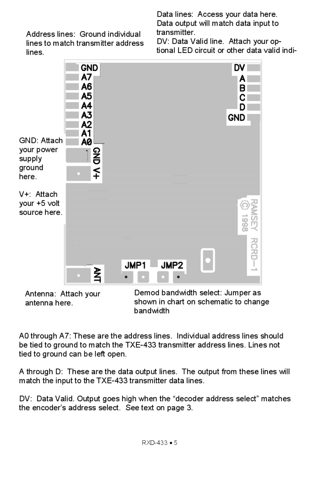
Address lines: Ground individual lines to match transmitter address lines.
Data lines: Access your data here. Data output will match data input to transmitter.
DV: Data Valid line. Attach your op- tional LED circuit or other data valid indi-
GND: Attach ![]()
![]()
![]() your power
your power ![]()
![]()
![]()
supply ground here.
V+: Attach ![]() your +5 volt
your +5 volt ![]()
![]()
![]()
![]() source here.
source here. ![]()
![]()
![]()
Antenna: Attach your | Demod bandwidth select: Jumper as |
antenna here. | shown in chart on schematic to change |
| bandwidth |
A0 through A7: These are the address lines. Individual address lines should be tied to ground to match the
A through D: These are the data output lines. The output from these lines will match the input to the
DV: Data Valid. Output goes high when the “decoder address select” matches the encoder’s address select. See text on page 3.