Operation (Continued)
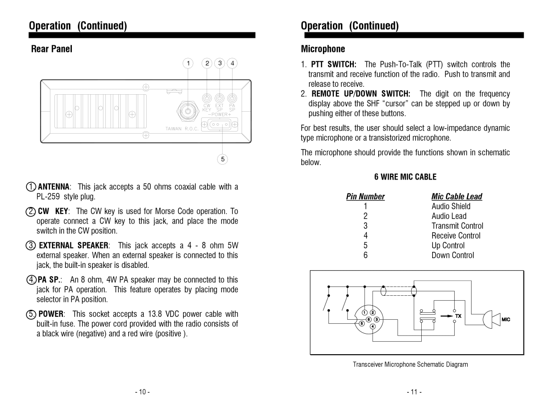
Rear Panel
1 2 3 4
5
1.ANTENNA: This jack accepts a 50 ohms coaxial cable with a
2.CW KEY: The CW key is used for Morse Code operation. To operate connect a CW key to this jack, and place the mode switch in the CW position.
3.EXTERNAL SPEAKER: This jack accepts a 4 - 8 ohm 5W external speaker. When an external speaker is connected to this jack, the
4.PA SP.: An 8 ohm, 4W PA speaker may be connected to this jack for PA operation. This feature operates by placing mode selector in PA position.
5.POWER: This socket accepts a 13.8 VDC power cable with
Operation (Continued)
Microphone
1.PTT SWITCH: The
2.REMOTE UP/DOWN SWITCH: The digit on the frequency display above the SHF “cursor” can be stepped up or down by pushing either of these buttons.
For best results, the user should select a
The microphone should provide the functions shown in schematic below.
6 WIRE MIC CABLE
Pin Number | Mic Cable Lead | ||
1 | Audio Shield | ||
2 | Audio Lead | ||
3 | Transmit Control | ||
4 | Receive Control | ||
5 | Up Control | ||
6 | Down Control | ||
|
|
|
|
|
|
|
|
|
|
|
|
|
|
|
|
|
|
|
|
Transceiver Microphone Schematic Diagram
- 10 - | - 11 - |