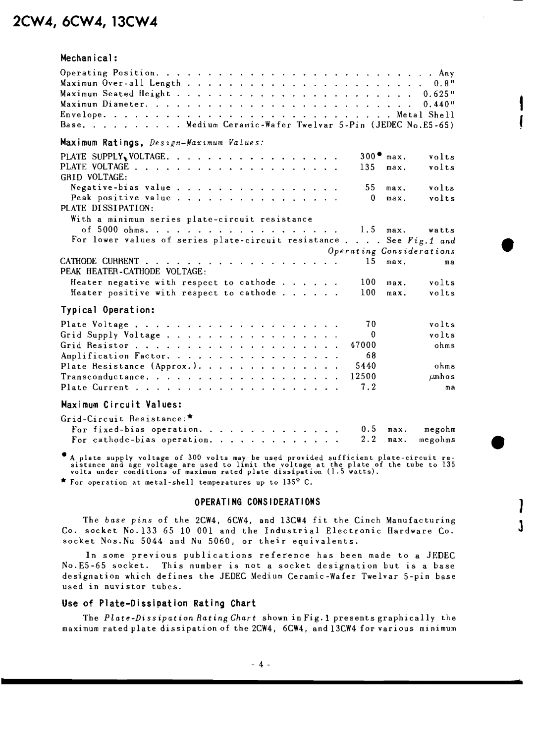
2CVV4, 6CVV4, 13CVV4
Mechan i ca1:
Operating Position. |
| . | . Any | ||
Maximum |
|
| 0.8" | ||
Maximum Seated Height |
|
| 0.625 " | ||
Maximum Diameter. |
|
| 0.440" | ||
Envelope. |
|
| Metal | Shell | |
Base . • | Medium | ||||
Maximum Ratings, |
|
|
| ||
PLATE | SUPPLY~VOLTAGE. | 300· max. | volts | ||
PLATE | VOLTAGE . |
| 135 | max. | volts |
GRID VOLTAGE: |
| 55 |
|
| |
value | max. | volts | |||
Peak | positive | value | 0 | max. | volts |
PLATE | DISSIPATION: |
|
|
| |
With a minimum series |
|
|
| ||
of | 5000 ohms. | 1.5 | max. | watts | |
For lower values of series |
| See Fig.l and | |||
|
| Operating Considerations | |||
CATHODE CURRENT | 15 | max. | ma | ||
PEAK | 100 | max. |
| ||
Heater negative with respect to cathode | volts | ||||
Heater positive with respect to cathode | 100 | max. | volts | ||
Typical Operation: |
|
|
| ||
Plate | Voltage . . | 70 |
| volts | |
Grid Supply Voltage | o |
| volts | ||
Grid Resistor . . . | 47000 |
| ohms | ||
Amplification Factor. | 68 |
|
| ||
Plate | Resistance | (Approx.). | 5440 |
| ohms |
Transconductance. | 12500 |
| |||
Plate | Current . |
| 7.2 |
| ma |
Maximum Circuit | Values: |
|
|
| |
0.5 | max. |
| |||
For | megohm | ||||
For | 2.2 | max. megohms | |||
•A plate supply voltage of 300 volts may be used provided sufficient
•For operation at
OPERATING CONSIDERATIONS
The base ptns of the 2CW4, 6CW4, and 13CW4 fit the Cinch Manufacturing Co. socket No.133 65 10 001 and the Industrial Electronic Hardware Co. socket Nos.Nu 5044 and Nu 5060, or their equivalents.
In some previous publications reference has been made to a JEDEC
Use of Plate-Dissipation Rating Chart
The
maximum rated plate dissipation of the 2CW4, 6CW4, and 13CW4 for various minimum
,r
•
•
1
1
- 4
