2CVV4, 6CVV4, 13CVV4
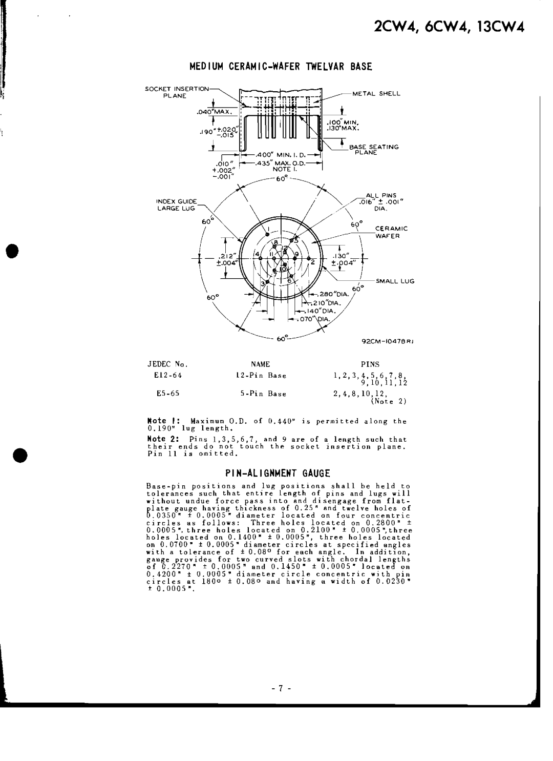
MEDIUM CERAMIC-WAFER TWELVAR BASE
SOCKET INSERTION
PLANE | METAL SHELL |
•
INDEX GUIDE
LARGE LUG
600
. 280 "OIA•
• 21O''olA •
•140"OIA .
•070' lA.
SMALL LUG
•
JEDEC | No. | NAME | PINS |
| |
Base | 1,2,3,4,5,6,7,8, | ||||
|
|
|
| 9,10,11,12 | |
Base | 2,4,8,10,12, | 2) | |||
|
|
|
| (Note | |
Note | I: | Maximum O.D. of | O.440 u is | permitted along | the |
0.190" lug length. |
|
|
| ||
Note 2: Pins 1,3,5,6,7, and 9 are of a length such that
their ends do not touch the socket insertion plane .
Pin 11 is omitted.
PIN-ALIGNMENT GAUGE
circles as follows: Three holes located on 0.2800" ± 0.0005". three holes located on 0.2100" ± O.OOOS",three holes located on 0.1400" ± 0.0005", three holes located on 0.0700" ± 0.0005" diameter circles at specified an~les with a tolerance of ± 0.08 0 for each angle. In additIon, gauge provides for two curved slots with chordal lengths of 0.2270" ± 0.0005" and 0.1450" ± 0.0005" located on 0.4200" ± 0.0005" diameter circle concentric with pin circles at 1800 ± 0.080 and having a width of 0.0230"
t0.0005".
- 7 -