Manuals
/
RCA
/
Home Audio
/
Cassette Player
RCA
CDP18S711
manual
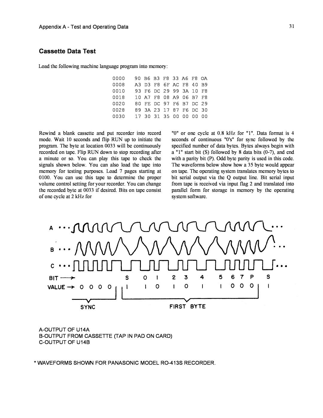
Cassette Data Test
Models:
CDP18S711
1
30
55
55
Download
55 pages
39.85 Kb
27
28
29
30
31
32
33
34
Troubleshooting
Appendix E - Logic Diagrams
Pin Signal
Testing Your Cassette System
The Power Supply
Using the Operating System
Page 30
Image 30
Page 29
Page 31
Page 30
Image 30
Page 29
Page 31
Contents
Page
RCA COSMAC VIP CDP18S711 Instruction Manual
VIP-311
ACKNOWLEDGMENT
Contents
Contents Continued
1. Getting Started
What This Manual Covers
The Power Supply
What You See
Turning It On
1. Getting Started
Using the Operating System
11.COSMAC VIP Operation
Memory Write
Memory Read
Tape Write
Tape Read
Testing Your Cassette System
11.COSMAC VIP Operation
How to Change and Use the Variables
III.CHIP-8Language Programming
Branch Instructions
Using the Display Instructions
0206 D125 SHOW 5MI@VlV2 0208 1208 GO 020A F090
III. CHIP-8 Language Programming
0200 A20A I=020A 0202 6100 V1=00 0204 6200 V2=00
020C F090 020E F000
Applying CHIP-8
Some Program Ideas
111. CHIP-8Language Programming
25.PROGRAMMED SPOT - Introduce children to programming concepts by letting them preprogram the movements of a spot or object on the screen
IV. Machine Language Programming
VIP Machine Coding
Machine Language Programming Summed Up
V. Logic Description
How Memory Is Addressed
How the Input/Output Works
pressed. A 62 machine instruction causes the least significant 4 bits of memory byte to be latched into U13. These 4 bits are decoded to bring one of the 16 U13 output lines low. If the key that corresponds to this output line is pressed, the CDPI802 EF3 input will go low. The 4-bitcodes latched into U13 correspond to the equivalent key positions. After the program send8 a 4-bitcode to U13, it subsequently examines the EF3 line to see if the key corresponding to this code is pressed or not. In this manner, a program can determine when any specific key is pressed or can sequentially scan all keys while waiting for any one to be pressed. Key debounce delays must be provided in the program when required. A program can also cause a speaker tone to occur when a key is pressed. Only one key at a time should be pressed with this method of interfacing the keyboard
Using the Byte Input/Output
V1. Expansion Considerations and Connections
Using the Expansion Interface
Some Expansion Ideas
I RCA COSMAC VIP Instruction Manual
Pin Signal
V1. Expansion Considerations and Connections
Table III - External Option Terminal Connections
2.Composing poetry or pictures with printer output
Signal Tracing
VIL Troubleshooting Hints
Other Problems
No Sound
Last Resorts
Appendix A - Test and Operating Data
Byte Pattern for Displaying COSMAC
Beeper Program
Cassette Attachment Diagram Cassette Phase Test
Signals
Test Program
Cassette Data Test
Cassette Recording Guidelines
Memory Test Program
Appendix B - Operating System
Operating System Listing
Operating System Register Table
Operating System Summary
R3 = Machine Language Subroutine Program Counter
Appendix C - CHIP-8Interpreter
CHIP-8Interpreter Listing
CHIP-8Memory Map
CDP1802 Register Use for CHIP-8
Interpreter
Appendix C - CHIP-8Interpreter
CHIP-8User Notes
RCA COSMAC VIP Instruction Manual
Page
1. VIP Kaleidoscope
2. VIP Video Display Drawing Game
Fig. E-1Microprocessor and Display Interface
Appendix E - Logic Diagrams
Fig. E-5Power Supply Circuit and Byte
Circuits
Page
Fig. E-2- ROM Circuits and Expansion Interface
Appendix E - Logic Diagrams
Page
Fig. E-4- RAM Circuits
Appendix E - Logic Diagrams
RCA COSMAC VIP Instruction Manuel
RCA COSMAC VIP Instruction Manual
2.Parts List for RCA COSMAC VIP CDP18S711
Board Layout, Parts List, and Expansion Notes
Appendix F
1.Printed Circuit Board Layout
RCA COSMAC VIP Instruction Manual
Page
2. Parts List for RCA COSMAC VIP CDP18S711
Page
RCA COSMAC VIP Instruction Manual
Resistors - Supplied 1 /4 W except as noted
Page
3. COSMAC VIP Expansion Notes
Top
Page
Image
Contents