user manual
RTD315W
FCC Information
This device complies with Part 15 of the FCC Rules. Operation is subject to the following two conditions: (1) This device may not cause harmful interference, and (2) this device must accept any interference received, including interference that may cause undesired operation.
This equipment has been tested and found to comply with the limits for a Class B digital device, pursuant to Part 15 of the FCC Rules. These limits are designed to provide reasonable protection against harmful interference in a residential installation. This equipment generates, uses and can radiates radio frequency energy and, if not installed and used in accordance with the instructions, may cause harmful interference to radio communications.
However, there is no guarantee that interference will not occur in a particular installation. If this equipment does causeharmful interference to radio or television reception, which can be
and on, the user is encouraged to try to correct the interferebce by one or more of
Ventilation
You must adequately ventilate the product. Make sure there is adequate space around
ventilation. See diagram.
7 cm
10 cm![]() 10 cm
10 cm
7 cm
10 cm ![]()
This product complies with DHHS Rules 21 CFR Subchapter J. Applicable at the date of manufacture.
For your safety
The AC power plug is polarized (one blade is wider than the other)
and onl![]() ts into AC power outlets one way. If the plug won’t go into
ts into AC power outlets one way. If the plug won’t go into
FCC Information
THE LIGHTNING FLASH AND ARROWHEAD
WITHIN THE TRIANGLE IS A WARNING
SIGN ALERTING YOU OF "DANGEROUS
VOLTAGE" INSIDE THE PRODUCT.
THE EXCLAMATION POINT WITHIN THE
TRIANGLE IS A WARNING SIGN ALERTING
YOU OF IMPORTANT INSTRUCTIONS
ACCOMPANYING THE PRODUCT.
CAUTION : TO REDUCE THE RISK OF ELECTRIC SHOCK, DO NOT REMOVE COVER (OR BACK). NO USER SERVICEABLE PARTS INSIDE. REFER SERVICING TO QUALIFIED SERVICE
PERSONNEL.
CAUTION : USE OF CONTROLS OR ADJUSTMENTS OR PERFORMANCE OF PROCEDURES OTHER THAN THOSE SPECIFIED MAY RESULT IN HAZARDOUS RADIATION EXPOSURE.
CAUTION : DANGER OF EXPLOSION IF BATTERY IS INCORRECTLY REPLACED.
Important Information
Important battery information
new and old batteries. Do not use rechargeable batteries.
observe the polarities indicated inside the battery compartment. Replace only with
![]() echarge them.
echarge them.
a long period of time, remove the batteries.
Please respect the environment
and prevailing regulations. Before you dispose of batteries or accumulators, ask your dealer whether they are subject to special recycling and if they will
accept them for disposal.
Illustrations contained in this document are for representation only.
Important Safety Instructions
CAUTION
controls or adjustments or performance of procedures other than those
open covers and do not repair yourself.
liquids, such as vases, should be placed on the apparatus.
This Class B digital apparatus complies with Canadian
Cet appareil numérique de la classe B est conforme à la norme
du Canada
WARNING
placed on the apparatus.
the following measures:
the outlet completely, turn the plug over and try to insert it the other
REPLACE ONLY WITH THE SAME OR EQUIVALENT TYPE.
Please read and save for future reference
• Do not defeat the safety purpose of the polarized or |
with one wider than the other. A grounding type plug |
DVD Home Theater System
AUDIO IN
It is important to readthis instruction book prior to using your new product for the![]() time.
time.
•Reorient or relocate the receiving antenna.
•Increase the separation between the equipment and receiver.
•Connect the equipment into an outlet on receiver is connected.
•Consult the dealer or an experienced radio/TV technician for help.
unit not expressly approved by the party responsible for compliance could void the user's authority to operate the equipment.
This Home Theater has earned the ENERGY STAR.
way.
electrician to change the outlet, or use a
safety feature.
Removing the power plug is the only way to completely remove power from your product. Make sure the power plug remains easily accessible.
Note:
This DVD player is designed and manufactured to respond to the Region Management Information. If the Region number of a DVD disc does not correspond to the Region number of this DVD player, this player cannot play the disc. The Region number for this DVD player is Region 1.
Service information
This product should be serviced only by those specially trained in appropriate servicing techniques.
Main plug is used as the disconnect device, it shall remain operable and should not be obstructed during intended use. To be completely disconnected the apparatus from supply mains, the main plug of the apparatus shall be disconnected from the mains socket outlet completely.
Caution
Invisible laser radiation when open. Avoid exposure to beam. Class 1 laser product.
technicians to prevent accidents caused by the laser beam.
DVD copy protection
In accordance with the DVD standard, your DVD player is equipped with a Copy Protection system, which can be switched on
an![]() he DVD disc itself, in order to make any recording of the relevant DVD disc onto a videotape of very poor picture quality, or even impossible. This product incorporates copyright protection technology that is protected by method claims of certain U.S. patents and other intellectual property rights owned by Macrovision Corporation and other rights owners. Use of this copyright protection technology must be authorized by Macrovision Corporation, and is intended for home use only unless otherwise authorized by Macrovision Corporation. Reverse engineering or disassembly
he DVD disc itself, in order to make any recording of the relevant DVD disc onto a videotape of very poor picture quality, or even impossible. This product incorporates copyright protection technology that is protected by method claims of certain U.S. patents and other intellectual property rights owned by Macrovision Corporation and other rights owners. Use of this copyright protection technology must be authorized by Macrovision Corporation, and is intended for home use only unless otherwise authorized by Macrovision Corporation. Reverse engineering or disassembly
is prohibited.
Some of the following information may not apply to your particular product; however, as with any electronic product, precautions should be observed during handling and use.
•Read these instructions.
•Keep these instructions.
•Heed all warnings.
•Follow all instructions.
•Do not use this apparatus near water.
•Clean only with dry cloth.
•Do not block any ventilation openings. Install in accordance with the manufacturer’s instructions.
•Do not install near any heat sources such as radiators,heat registers, stoves, or other
| produce heat. |
|
• | Only use attachments/accessories | ] |
|
|
has two blades and a third grounding prong. |
The wide blade or the third prong is provided for |
outlet, consult an electrician for electrician for replacement of the obsolete outlet.
•Protect the power cord from being walked on or pinched particularly at plugs, convenience receptacles, and the point where they exit from the apparatus.
•Use only with the cart, stand, tripod, bracket,
sold with the apparatus. When a cart is used, use caution when moving the cart/apparatus combination to avoid injury from
•Unplug this apparatus during lightning storms or when unused for long periods of time.
•
Servicing is required when the apparatus has been damaged in any way, such as
- 2 -
- 3 -
Portable Cart Warning
- 4 - does not operate normally, or has been dropped
Important Safety Instructions
Additional safety information
•Apparatus shall not be exposed to dripping
liquids, such as vases, shall be placed on the apparatus.
•
product for ventilation. Do not place product in or on a bed, rug, in a bookcase or cabinet
vent openings.
• | Do not place lighted candles, cigarettes, |
| cigars, etc. on the product. |
• | Connect power cord only to AC power |
If your product operates on batteries, adhere to the following precautions: A.Any battery may leak electrolyte if mixed
incorrectly, or if all batteries are not replaced at the same time.
B. Any battery may leak electrolyte or explode
to charge a battery not intended to be recharged.
C. Discard leaky batteries immediately. Leaking batteries can cause skin burns or other personal injury. When discarding batteries,
Connections and Setup
• | Where the mains plug or an appliance coupler | Method 2 |
|
| |
Component video jacks (Pr, Pb, Y) |
| ||||
| is used as a disconnect device, the disconnect |
| |||
| • The component video jacks are | ||||
| device shall remain readily operable. | ||||
|
| green, blue and red. |
| ||
• | Other important use and cleaning information at |
|
| ||
• | Additional component video cables (not | ||||
| the end of the manual. |
| supplied) are required to provide best picture | ||
| Connecting the antennas |
| quality. They are usually | green, | |
|
| blue and red. |
|
| |
| FM75 Ω | • | Connect the | component video OUT jacks | on the |
|
| receiver to | the component video IN jacks on | ||
|
|
| |||
| White |
| your TV so the video content goes from the | ||
|
| receiver to the screen. |
| ||
Connections and Setup
Notes:
•Refer to the owner’s manual of the connected TV as well
•When using HDMI cable, do not connect to other analog video outputs.
Connecting AUDIO from external sources such as TV
Using AUX IN
Connect the AUX IN jacks on rear of the unit to the AUDIO OUT jacks on VCR, TV, Set Top Box or other component. Press either SOURCE on the main unit or AUDIO/AUX on the remote control to toggle select AUX IN mode.
Notes:
•Ø3.5mm to Ø3.5mm audio cables (not included) are required.
•To listen to the audio input from the connected component, press SOURCE on the main unit or
AUDIO / AUX on the remote control to toggle to AUDIO IN mode.
Suggest using Ø3.5mm
AUDIO IN jack for mp3 ![]() player and rear AUX IN jacks
player and rear AUX IN jacks
for equipment such as a TV,
Connections and Setup
Speaker wires are
Note: When connecting the speakers, make sure the polarities (“+” speaker wire to “+” on the receiver.
For example, red wire to red terminal on the receiver) of speaker wires and terminals match. If the cords are reversed, the sound will be distorted. Do not let the speaker wires touch each other, it will damage the Home Theater’s amplifer.
| source as marked on the product. |
• | Care should be taken so that objects do not |
| fall into the product. |
• | Do not attempt to disassemble the cabinet. |
| This product does not contain customer |
| serviceable components. |
be sure to dispose of them in the proper manner, according to your state/provincial and local regulations.
D. Battery shall not be exposed to excessive
Antenna |
| |
| • | |
GND | television, use the unit’s HDMI output | |
to get the highest possible video resolution. | ||
| ||
The AM and FM antennas connect to the | If unable to use a HDMI connection, use the unit’s | |
AM and FM terminals on the system’s back | component video output and set the Progressive |
TV
VCR | Set Top Box AUDIO OUT |
OR | OR |
VCR, Satellite or Cable Box.
Digital Optical Input
Connect components capable of outputting Dolby Digital (e.g. TV or Set Top Box) or standard PCM (CD) format digital signals.
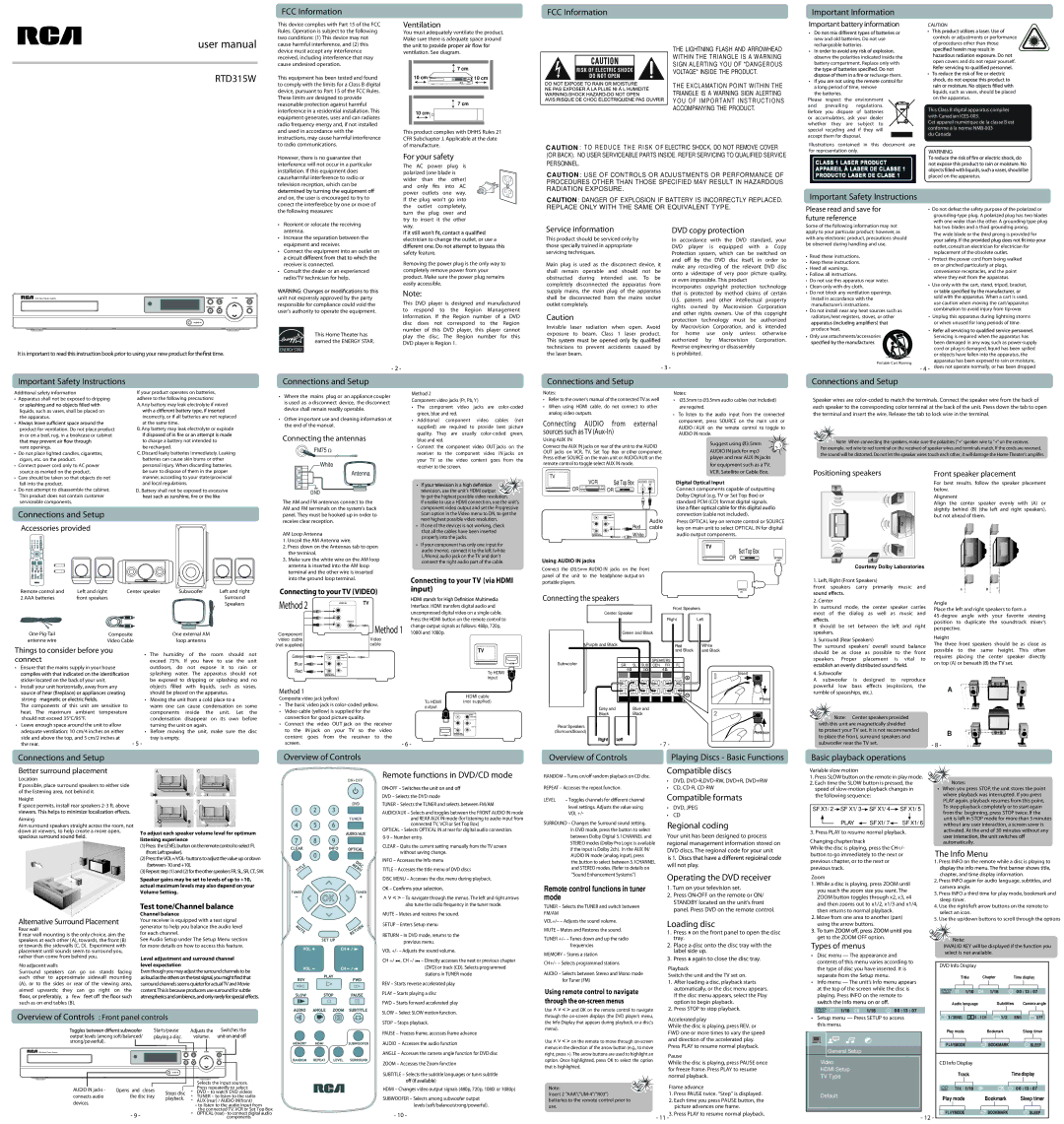
Positioning speakers
3 |
1 |
Front speaker placement
For best results, follow the speaker placement below.
Alignment
Align the center speaker evenly with (A) or slightly behind (B) (the left and right speakers),
Connections and Setup
Accessories provided
+ | - |
+ | - |
Remote control and | Left and right | Center speaker | Subwoofer | Left and right | |||
2 AAA batteries | front speakers |
|
|
|
| Surround |
|
|
|
|
|
|
| Speakers |
|
One | Composite |
| One external AM |
|
|
| |
antenna wire | Video Cable |
| loop antenna |
|
|
| |
Things to consider before you |
| • The humidity of the | room | should | not | ||
connect |
|
| |||||
|
| exceed 75%. If you have to use the unit | |||||
• Ensure that the mains supply in your house |
| outdoors, do not expose it to rain or | |||||
|
|
| splashing water. The apparatus should not | ||||
sticker located on the back of your unit. |
| be exposed to dripping or splashing and no | |||||
• Install your unit horizontally, away from any |
| objects | led with liquids, such as vases, | ||||
|
|
| should be placed on the apparatus. |
| |||
stron |
|
| • Moving the unit from a cold place to a |
| |||
The components of this unit are sensitive to | warm one can cause condensation on some | ||||||
heat. The maximum ambient temperature | components inside the unit. Let the | ||||||
should not exceed 35°C/95°F. |
| condensation disappear on its own before | |||||
• Leave enough space around the unit to allow |
| turning the unit on again. |
|
|
| ||
adequate ventilation: 10 cm/4 inches on either |
| • Before | moving the unit, | make | sure the | disc | |
side and above the top, and 5 cm/2 inches at | - 5 - | tray is empty. |
|
|
| ||
the rear. |
|
|
|
|
|
| |
panel. They must be hooked up in order to | Scan option in the Video menu to ON, to get the | |||
receive clear reception. |
|
| next highest possible video resolution. | |
|
| • If one of the devices is not working, check | ||
|
|
| ||
AM Loop Antenna |
|
| that all the cables have been inserted | |
|
| properly into the jacks. | ||
1. Uncoil the AM Antenna wire. |
|
| ||
|
| • If your component has only one input for | ||
2. Press down on the Antennas tab to open | ||||
audio (mono), connect it to the left (white | ||||
the terminal. |
|
| ||
|
| L/Mono) audio jack on the TV and don’t | ||
3. Make sure the white wire on the AM loop | ||||
connect the right audio part of the cable. | ||||
antenna is inserted into the AM loop |
| |||
|
| |||
terminal and the other wire is inserted | Connecting to your TV (via HDMI | |||
into the ground loop terminal. |
|
| ||
Connecting to your TV (VIDEO) | input) | |||
| ||||
Method 2 | TV |
| Interface. HDMI transfers digital audio and | |
|
| |||
|
|
| uncompressed digital video on a single cable. | |
|
|
| Press the HDMI button on the remote control to | |
|
| Method 1 | change output signals as follows: 480p, 720p, | |
Component |
| 1080i and 1080p. | ||
video cable |
| Video |
| |
(not supplied) |
| cable | TV | |
Green |
|
| ||
|
|
| ||
Blue |
|
| HDMI | |
|
|
| ||
| AUX IN |
Red | To HDMI |
| |
| input |
Method 1
Composite video jack (yellow) |
|
|
|
| To HDMI | HDMI cable | |||
• The basic video jack is | (not s upplied) | ||||||||
output |
| ||||||||
• Video cable (yellow) is supplied for the |
|
| |||||||
|
|
| |||||||
connection for good picture quality. |
|
|
| ||||||
• Connect | the video | OUT jack | on | the | receiver | AUX IN | |||
to the | IN jack | on | your | TV | so | the | video |
| |
content | goes | from the | receiver | to | the | HDMI | |||
screen. |
|
|
|
|
|
|
| - 6 - |
|
|
|
| connection (cable not included). |
| ||
| Red | Audio | Press OPTICAL key on remote control or SOURCE | |||
AUX IN | cable | key on main unit to select OPTICAL IN for digital | ||||
| White |
| audio output components. |
|
| |
|
|
|
| TV | Set Top Box |
|
|
|
|
| OR |
| |
Using AUDIO IN jacks |
|
|
|
| OPTICAL | |
|
|
|
|
| OUT | |
Connect the Ø3.5mm AUDIO IN jacks on the front |
|
|
|
|
| |
panel of the unit to the headphone output on |
|
|
|
|
| |
portable players. |
|
|
|
|
|
|
|
|
|
|
| OPTICAL |
|
Connecting the speakers |
|
|
|
| IN |
|
|
|
|
|
|
| |
Center Speaker |
| Front Speakers |
|
| ||
|
|
|
|
| ||
|
|
| Right | Left |
|
|
| Green and Black |
|
|
|
| |
Purple and Black |
|
| Red | White |
|
|
|
|
| and Black | and Black |
|
|
Subwoofer |
|
|
| SPEAKERS |
| ||
SR | SL | SUB | CEN | FR | FL | ||
| |||||||
| 4 |
| 3 |
| 4 | Insert | |
|
|
|
|
|
| ||
|
|
|
|
|
| Press | |
| Grey and | Blue and |
|
|
| ||
| Black | Black |
|
|
| ||
Rear Speakers |
|
(SurroundSound) | Release |
- 7 - |
| 2 |
| 1 |
3 | 4 |
Courtesy Dolby Laboratories
1. Left, Right (Front Speakers)
Front speakers carry primarily music and
2. Center
In surround mode, the center speaker carries most of the dialog as well as music and
It should be set between the left and right speakers.
3. Surround (Rear Speakers)
The surround speakers’ overall sound balance should be as close as possible to the front speakers. Proper placement is vital to
4. Subwoofer
A subwoofer is designed to reproduce
powerful low bass ![]() ects (explosions, the rumble of spaceships, etc.).
ects (explosions, the rumble of spaceships, etc.).
![]()
![]() Note: Center speakers provided with this unit are magnetically shielded
Note: Center speakers provided with this unit are magnetically shielded
to protect your TV set. It is not recommended to place the front, surround speakers and subwoofer near the TV set.
but not ahead of them.
Angle
Place the left and right speakers to form a
Height
The three front speakers should be as close as possible to the same height. This often requires placing the center speaker directly on top (A) or beneath (B) the TV set.
A
B
- 8 -
Connections and Setup | Overview of Controls |
Overview of Controls | Playing Discs - Basic Functions |
Basic playback operations
Better surround placement
Location
If possible, place surround speakers to either side of the listening area, not behind it.
Remote functions in DVD/CD mode
ON•OFF – S![]()
RANDOM – Turns on/off random playback on CD disc. | Compatible discs | ||
• | DVD, | ||
| |||
REPEAT – Accesses the repeat function. | • | CD, | |
Variable slow motion |
|
1. Press SLOW button on the remote in play mode. | Notes: |
2. Each time the SLOW button is pressed, the | |
speed of | • When you press STOP, the unit stores the point |
Height
If space permits, install rear speakers
Aiming
Aim surround speakers straight across the room, not down at viewers, to help create a more open,
Alternative Surround Placement
Rear wall
If rear wall mounting is the only choice, aim the speakers at each other (A), towards, the front (B) or towards the sidewalls (C, D). Experiment with placement until sounds seem to surround you, rather than come from behind you.
No adjacent walls
Surround speakers can go on stands facing each other to approximate sidewall mounting
(A), or to the sides or rear of the viewing area, aimed upwards; they can go right on the ![]() bly, a few
bly, a few ![]() such as on end tables (B).
such as on end tables (B).
To adjust each speaker volume level for optimum listening experience
(1)Press the LEVELbuttononthe remotecontroltoselectFL (frontLeftspeaker).
(2)Pressthe
(3)Repeatstep(1)and(2)fortheotherspeakersFR,SL,SR,CT, SW.
Speaker gains may be set to levels of up to +10, actual maximum levels may also depend on your Volume Setting.
Test tone/Channel balance
Channel balance
Your receiver is equipped with a test signal generator to help you balance the audio level for each channel.
See Audio Setup under The Setup Menu section for more details on how to access this feature.
Level adjustment and surround channel level expectation
Eventhoughyoumayadjustthe surroundchannelstobe
surround channelsseemsquieterforactualTVandMovie content.Thisis becauseproducersusesurroundforsubtle
DVD – Selects the DVD mode
TUNER – Selects the TUNER and selects between FM/AM
AUDIO/AUX – Selects and toggles between the FRONT AUDIO IN mode and REAR AUX IN mode (for listening to audio input from connected TV, VCR or Set Top Box)
OPTICAL – Selects OPTICAL IN at rear for digital audio connection.
CLEAR – Quits the current setting manually from the TV screen without saving change.
INFO – Accesses the Info menu
TITLE – Accesses the title menu of DVD discs
DISC MENU – Accesses the disc menu during playback.
OK –
![]()
![]()
![]()
![]() – To navigate through the menus. The left and right arrows also tune the radio frequency in the tuner mode.
– To navigate through the menus. The left and right arrows also tune the radio frequency in the tuner mode.
MUTE – Mutes and restores the sound.
SETUP – Enters Setup menu
RETURN – In DVD mode, returns to the previous menu.
VOL +/- – Adjusts the sound volume.
CH +/ ![]()
![]() , CH
, CH ![]()
![]() – Directly accesses the next or previous chapter (DVD) or track (CD). Selects programmed stations in TUNER mode
– Directly accesses the next or previous chapter (DVD) or track (CD). Selects programmed stations in TUNER mode
REV – Starts reverse accelerated play PLAY – Starts playing a disc
FWD – Starts forward accelerated play
LEVEL – Toggles channels for different channel
level settings. Adjusts the value using VOL +/-
SURROUND – Changes the Surround sound setting. In DVD mode, press the button to select between Dolby Digital 5.1CHANNEL and STEREO modes (Dolby Pro Logic is available if the input is Dolby 2ch). In the AUX IN/ AUDIO IN mode (analog input), press
the button to select between 5.1CHANNEL and STEREO modes. (Refer to details on
“Sound Enhancement Systems”)
Remote control functions in tuner mode
TUNER – Selects the TUNER and switch between FM/AM
VOL+/– – Adjusts the sound volume. MUTE – Mutes and Restores the sound.
TUNER +/– – Tunes down and up the radio frequencies
MEMORY – Stores a station
CH+/– – Selects programmed stations
AUDIO – Selects between Stereo and Mono mode for Tuner (FM)
Using remote control to navigate through the
Compatible formats
•DVD, JPEG
•CD
Regional coding
Your unit has been designed to process regional management information stored on DVD discs. The regional code for your unit is 1![]()
will not play.
Operating the DVD receiver
1.Turn on your television set.
2.Press ON•OFF on the remote or ON/ STANDBY located on the unit’s front panel. Press DVD on the remote control.
Loading disc
1.Press ![]() on the front panel to open the disc tray.
on the front panel to open the disc tray.
2.Place a disc onto the disc tray with the label side up.
3.Press  again to close the disc tray.
Playback
Switch the unit and the TV set on.
1. After loading a disc, playback starts |
automatically, or the disc menu appears. |
If the disc menu appears, select the Play |
option to begin playback. |
the following sequence: |
|
|
| where playback was interrupted. If you press | |||||||||||
|
|
|
|
|
|
|
|
|
|
|
|
|
| PLAY again, playback resumes from this point. | |
|
|
|
|
|
|
|
|
|
|
|
|
|
| To stop playback completely or to start again | |
SF X1/ 2 |
| SF X1/ 3 |
|
| SF X1/ 4 |
|
|
| SF X1/ 5 | ||||||
|
|
|
|
|
| from the beginning, press STOP twice. If the | |||||||||
|
|
|
|
|
|
|
|
|
|
|
|
|
| unit is left in STOP mode for more than 5 minutes | |
|
|
|
| PLAY |
|
|
| SFX1/ 7 |
|
| SF X1/ 6 | ||||
|
|
|
|
|
|
|
| without any user interaction, a screen saver is | |||||||
|
|
|
|
|
| ||||||||||
3. Press PLAY to resume normal playback. | activated. At the end of 30 minutes without any | ||||||||||||||
| |||||||||||||||
Changing chapter/track |
|
|
|
|
|
|
| automatically. | |||||||
While the disc is playing, press the CH+/- | The Info Menu | ||||||||||||||
button to go immediately to the next or | |||||||||||||||
previous chapter, or to the next or |
|
|
| 1. Press INFO on the remote while a disc is playing to | |||||||||||
previous track. |
|
|
|
|
|
|
| chapter, and time display information. | |||||||
Zoom |
|
|
|
|
|
|
| ||||||||
|
|
|
|
|
|
| 2. Press INFO again for audio language, subtitles, and | ||||||||
1. While a disc is playing, press ZOOM until | |||||||||||||||
camera angle. | |||||||||||||||
you reach the zoom size you want. The | |||||||||||||||
3. Press INFO a third time for play mode, bookmark and | |||||||||||||||
ZOOM button toggles through x2, x3, x4 | |||||||||||||||
sleep timer. | |||||||||||||||
and then zooms out to x1/2, x1/3 and x1/4, | |||||||||||||||
4. Use the right/left arrow buttons on the remote to | |||||||||||||||
then returns to normal playback. |
|
|
| ||||||||||||
|
|
| select an icon. | ||||||||||||
2. Move from one area to another (pan) | |||||||||||||||
5. Use the up/down buttons to scroll through the options | |||||||||||||||
using the arrow buttons. |
|
|
|
| |||||||||||
get to the ZOOM OFF option. |
|
|
| Note: | |||||||||||
Types of menus |
|
|
|
|
|
|
| ||||||||
|
|
|
|
|
|
| INVALID KEY will be displayed if the function you | ||||||||
• Disc menu — The appearance and | select is not available. |
|
| ||
|
|
|
| ||
contents of this menu varies according to | DVD Info Display |
|
|
| |
the type of disc you have inserted. It is |
|
|
| ||
|
|
|
| ||
separate from the Setup menu. | Title | Chapter | Time display | ||
• Info menu — The unit’s Info menu appears | |||||
|
|
|
| ||
at the top of the screen while the disc is | TT | CH |
|
| |
playing. Press INFO on the remote to |
|
| |||
|
|
|
| ||
| Audio language |
| Subtitles | Camera angle | |
Overview of Controls : Front panel controls
output levels (among soft/balanced/ | Starts/pause | Adjusts the | Switches the |
playing a disc. | volume. |
| |
strong/powerful). |
|
|
|
DVD Home Theater System |
|
|
|
| AUDIO IN |
|
|
SLOW – Select SLOW motion function.
STOP – Stops playback.
PAUSE – Freezes frame, accesses frame advance
AUDIO – Accesses the audio function
ANGLE – Accesses the camera angle function for DVD disc
ZOOM – Accesses the Zoom function
SUBTITLE – Selects the subtitle languages or tunrs subtitle
Use ![]()
![]()
![]()
![]() and OK on the remote control to navigate through the
and OK on the remote control to navigate through the
Use ![]()
![]()
![]()
![]() on the remote to move through
on the remote to move through
2. Press STOP to stop playback. |
Accelerated play
While the disc is playing, press REV. or FWD one or more times to vary the speed and direction of the accelerated play. Press PLAY to resume normal playback.
Pause
While the disc is playing, press PAUSE once for freeze frame. Press PLAY to resume normal playback.
TT | CH |
|
|
|
• Setup menu — Press SETUP to access |
| 5 . 1CH | OFF | |
this menu. |
|
|
|
|
|
| Play mode | Bookmark | Sleep timer |
|
| PLA |
|
|
General Setup |
|
|
| |
Video |
| CD Info Display |
|
|
HDMI Setup |
| Track |
| Time display |
TV Type |
|
| ||
|
|
|
| |
|
|
|
| Selects the input sources. | |
AUDIO IN jacks - | Opens and closes |
| • | Press repeatedly to select: | |
Stops disc | DVD – to watch DVD videos | ||||
connects audio | the disc tray. | • | TUNER – to listen to the radio | ||
playback. | |||||
devices. |
| • | AUX (rear) / AUDIO IN(front) | ||
|
|
| – to listen to the audio input from | ||
|
|
| • | the connected TV, VCR or Set Top Box | |
| - 9 - |
| OPTICAL (rear) - to connect digital audio | ||
|
|
| components |
HDMI – Changes video output signals (480p, 720p, 1080i or 1080p)
SUBWOOFER – Selects among subwoofer output levels (soft/balance/strong/powerful).
- 10 -
Note: | Frame advance | |
Insert 2 | 1. | Press PAUSE twice. “Step” is displayed. |
batteries to the remote control prior to | 2. Each time you press PAUSE button, the | |
use. |
| picture advances one frame. |
| - 11 | Press PLAY to resume normal playback. |
| TRK |
|
|
Default | Play mode | Bookmark | Sleep timer |
| |||
| PLA |
|
|
| - 12 - |
|
|