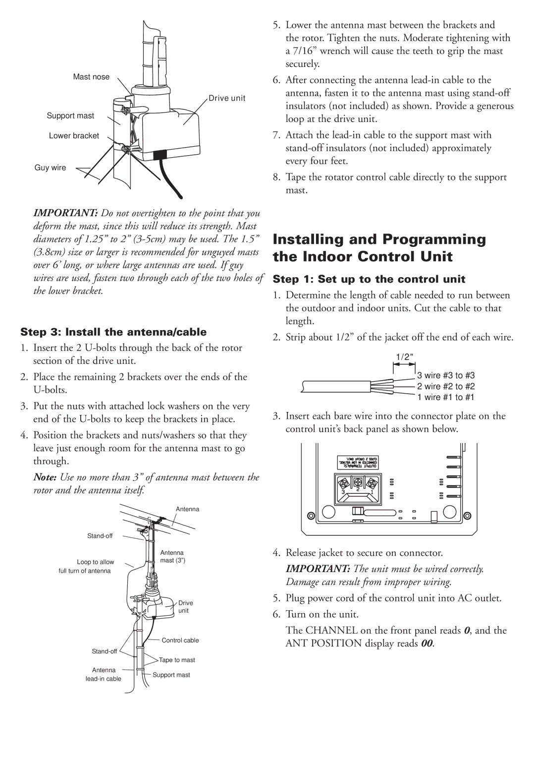
Mast nose
Drive unit
Support mast
Lower bracket
Guy wire
IMPORTANT: Do not overtighten to the point that you deform the mast, since this will reduce its strength. Mast diameters of 1.25” to 2”
Step 3: Install the antenna/cable
1.Insert the 2
2.Place the remaining 2 brackets over the ends of the
3.Put the nuts with attached lock washers on the very end of the
4.Position the brackets and nuts/washers so that they leave just enough room for the antenna mast to go through.
Note: Use no more than 3” of antenna mast between the rotor and the antenna itself.
5.Lower the antenna mast between the brackets and the rotor. Tighten the nuts. Moderate tightening with a 7/16” wrench will cause the teeth to grip the mast securely.
6.After connecting the antenna
7.Attach the
8.Tape the rotator control cable directly to the support mast.
Installing and Programming the Indoor Control Unit
Step 1: Set up to the control unit
1.Determine the length of cable needed to run between the outdoor and indoor units. Cut the cable to that length.
2.Strip about 1/2” of the jacket off the end of each wire.
1/2"
3 wire #3 to #3
2 wire #2 to #2
1 wire #1 to #1
3.Insert each bare wire into the connector plate on the control unit’s back panel as shown below.
| Antenna | |
| ||
| Antenna | |
Loop to allow | mast (3”) | |
full turn of antenna |
| |
| Drive | |
| unit | |
| Control cable | |
| ||
| Tape to mast | |
Antenna | Support mast | |
|
4.Release jacket to secure on connector.
IMPORTANT: The unit must be wired correctly. Damage can result from improper wiring.
5.Plug power cord of the control unit into AC outlet.
6.Turn on the unit.
The CHANNEL on the front panel reads 0, and the ANT POSITION display reads 00.