6. Set up
SE1 |
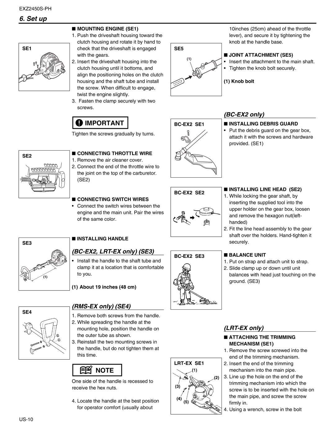
■MOUNTING ENGINE (SE1)
1.Push the driveshaft housing toward the clutch housing and rotate it by hand to check that the driveshaft is engaged with the gears.
2.Insert the driveshaft housing into the clutch housing until it bottoms, and align the positioning holes on the clutch housing and the shaft tube and install the screw. When difficult to engage, twist the engine slightly.
3.Fasten the clamp securely with two screws.
SE5 |
(1) |
10inches (25cm) ahead of the throttle lever), and secure it by tightening the knob at the handle base.
■JOINT ATTACHMENT (SE5)
•Insert the attachment to the main shaft.
•Tighten the knob bolt securely.
(1) Knob bolt
![]()
![]() IMPORTANT
IMPORTANT
Tighten the screws gradually by turns.
(BC-EX2 only)
■INSTALLING DEBRIS GUARD
•Put the debris guard on the gear box, attach it with the screws and hardware provided. (SE1)
SE2 |
■CONNECTING THROTTLE WIRE
1. Remove the air cleaner cover.
2. Connect the end of the throttle wire to the joint on the top of the carburetor. (SE2)
■CONNECTING SWITCH WIRES
•Connect the switch wires between the engine and the main unit. Pair the wires of the same color.
BC-EX2 SE2
■ INSTALLING LINE HEAD (SE2) | |
1. | While locking the gear shaft, by |
| inserting the supplied tool into the |
| upper holder on the gear box, loosen |
| and remove the hexagon nut(left- |
| handed) |
2. | Fit the line head assembly to the gear |
| shaft over the holders. |
SE3 |
(1) |
■INSTALLING HANDLE
(BC-EX2, LRT-EX only) (SE3)
•Install the handle to the shaft tube and clamp it at a location that is comfortable to you.
(1) About 19 inches (48 cm)
securely. |
■ BALANCE UNIT |
1.Put on strap and attach unit to strap.
2.Slide clamp up or down until unit balances with head just touching on the ground. (SE3)
SE4
(RMS-EX only) (SE4)
1. Remove both screws from the handle.
2. While spreading the handle at the mounting hole, position the handle on the outer tube as shown.
3. Reinstall the two mounting screws in the handle, but do not tighten them at this time.
![]() NOTE
NOTE
One side of the handle is recessed to receive the hex nuts.
4.Locate the handle at the best position for operator comfort (usually about
(LRT-EX only)
■ATTACHING THE TRIMMING MECHANISM (SE1)
1.Remove the screw screwed into the end of the trimming mechanism.
2.Insert the end of the trimming mechanism into the main pipe.
3.Line up the hole on the end of the trimming mechanism into which the screw is to be inserted with the hole on the main pipe, and screw the screw firmly in.
4.Using a wrench, screw in the bolt