Diagram 9
6.With the stop valve connected, flush the
7.The shower is designed to have an open outlet and should only be used with ‘Redring’ recommended fittings. Do not connect the showerhead until after the shower front cover and removable side section are fitted.
WARNING - DO NOT FIT A TAP ON THE SHOWER OUTLET. TAKE CARE TO AVOID RESTRICTING THE OUTLET AND FLOW FROM THE SHOWERHEAD OR THE PRESSURE RELIEF DEVICE.
d) Electrical Connections
The electrical installation must be in accordance with the current BS. 7671 (I.E.E. regulations). If in doubt consult a qualified electrician.
1.The shower is designed for a
2.
Cable Sizes | Fuse/ MCB |
|
9.5 / 8.7kW 240 / 230V |
|
|
10mm² | 40 or 45A Cartridge fuse |
|
10.5 / 9.6kW 240 / 230V |
|
|
10mm² | 45A Cartridge fuse / MCB | For the 9.5kW you |
|
|
may be able to use 6mm² cable if Method 1 (clipped direct) is used.
Remember to up rate the cable if it runs in thermal insulation in a loft, or for longer distance
3.A means for disconnection in all poles must be incorporated in the fixed wiring in accordance with the wiring rules. We recommend a ceiling switch mounted in a convenient position.
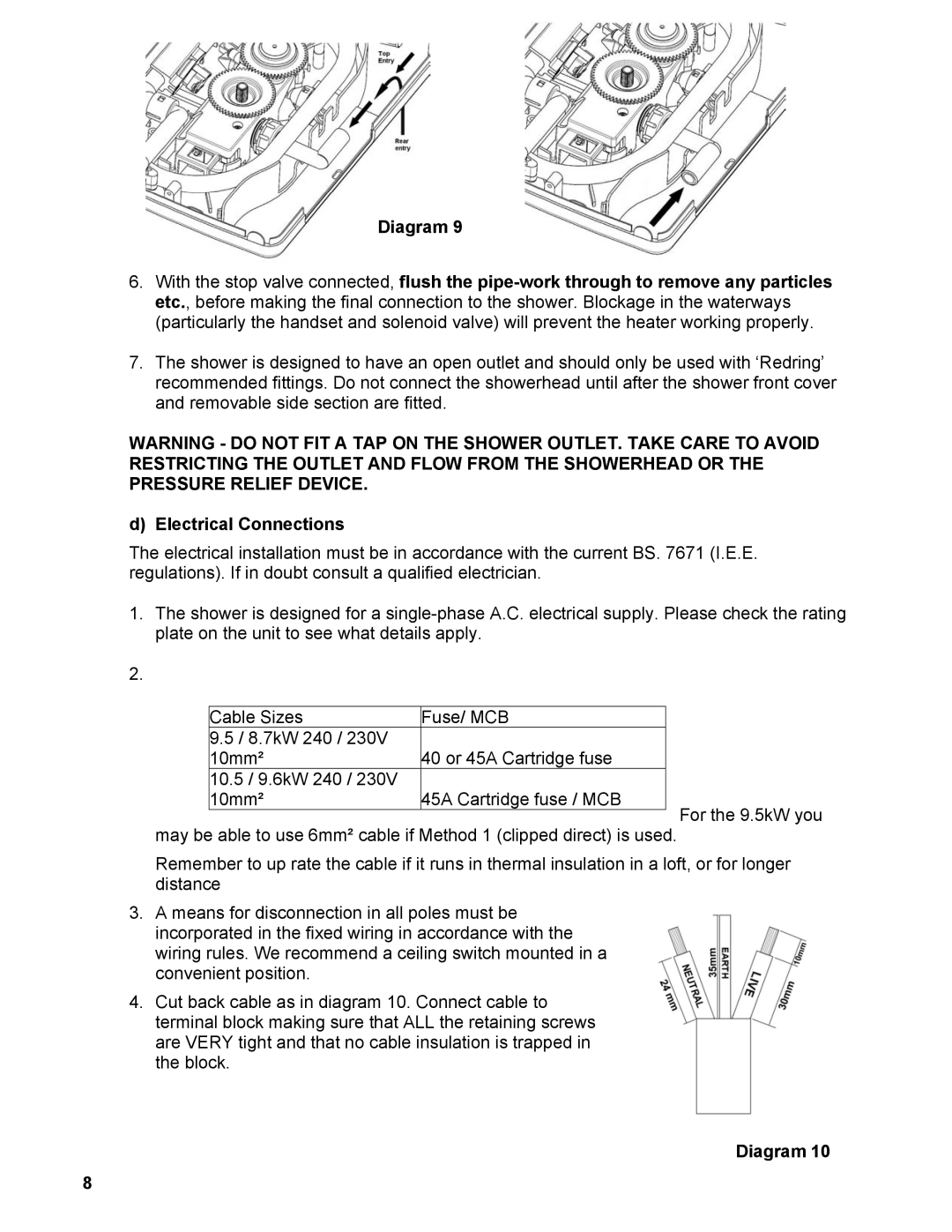
4.Cut back cable as in diagram 10. Connect cable to terminal block making sure that ALL the retaining screws are VERY tight and that no cable insulation is trapped in the block.
Diagram 10
8