ASSEMBLY
installing THE GUARD
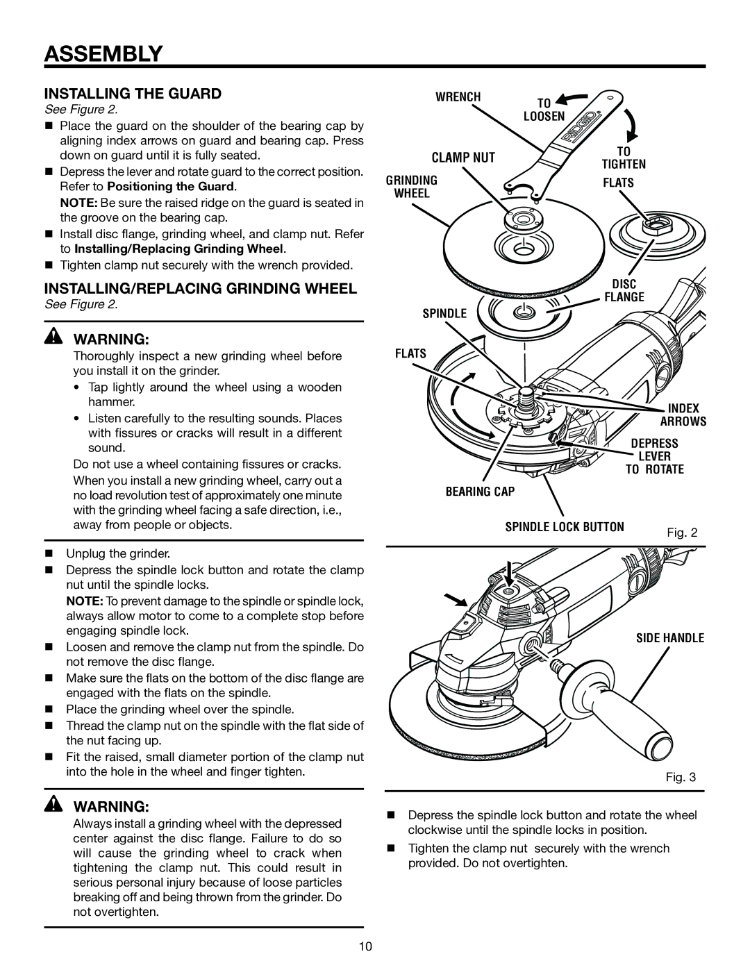
See Figure 2.
Place the guard on the shoulder of the bearing cap by aligning index arrows on guard and bearing cap. Press down on guard until it is fully seated.
Depress the lever and rotate guard to the correct position. Refer to Positioning the Guard.
NOTE: Be sure the raised ridge on the guard is seated in the groove on the bearing cap.
Install disc flange, grinding wheel, and clamp nut. Refer to Installing/Replacing Grinding Wheel.
Tighten clamp nut securely with the wrench provided.
INSTALLING/replacing GRINDING WHEEL
See Figure 2.
WARNING:
Thoroughly inspect a new grinding wheel before you install it on the grinder.
•Tap lightly around the wheel using a wooden
hammer .
•Listen carefully to the resulting sounds. Places with fissures or cracks will result in a different sound.
Do not use a wheel containing fissures or cracks.
When you install a new grinding wheel, carry out a no load revolution test of approximately one minute with the grinding wheel facing a safe direction, i.e., away from people or objects.
Unplug the grinder.
Depress the spindle lock button and rotate the clamp nut until the spindle locks.
Note: To prevent damage to the spindle or spindle lock, always allow motor to come to a complete stop before engaging spindle lock.
Loosen and remove the clamp nut from the spindle. Do not remove the disc flange.
Make sure the flats on the bottom of the disc flange are engaged with the flats on the spindle.
Place the grinding wheel over the spindle.
Thread the clamp nut on the spindle with the flat side of the nut facing up.
Fit the raised, small diameter portion of the clamp nut into the hole in the wheel and finger tighten.
WARNING:
Always install a grinding wheel with the depressed center against the disc flange. Failure to do so will cause the grinding wheel to crack when tightening the clamp nut. This could result in serious personal injury because of loose particles breaking off and being thrown from the grinder. Do not overtighten.
Wrench | to | |
| ||
| loosen | |
clamp NUT | to | |
tighten | ||
| ||
Grinding | flats | |
Wheel |
|
Disc
Flange
Spindle
flats
![]()
![]()
![]()
![]()
![]()
![]()
![]()
![]()
![]()
![]()
![]()
![]()
![]()
![]()
![]()
![]()
![]()
![]()
![]()
![]()
![]()
![]()
![]()
![]()
![]() index
index
arrows
depress
lever
![]()
![]()
![]()
![]()
![]()
![]()
![]()
![]()
![]()
![]()
![]()
![]()
![]()
![]() to ROTATE bearing cap
to ROTATE bearing cap
Spindle Lock Button | Fig. 2 |
|
side handle
Fig. 3
Depress the spindle lock button and rotate the wheel clockwise until the spindle locks in position.
Tighten the clamp nut securely with the wrench provided. Do not overtighten.
10