OPERATION
WIDTH OF CUT SCALE
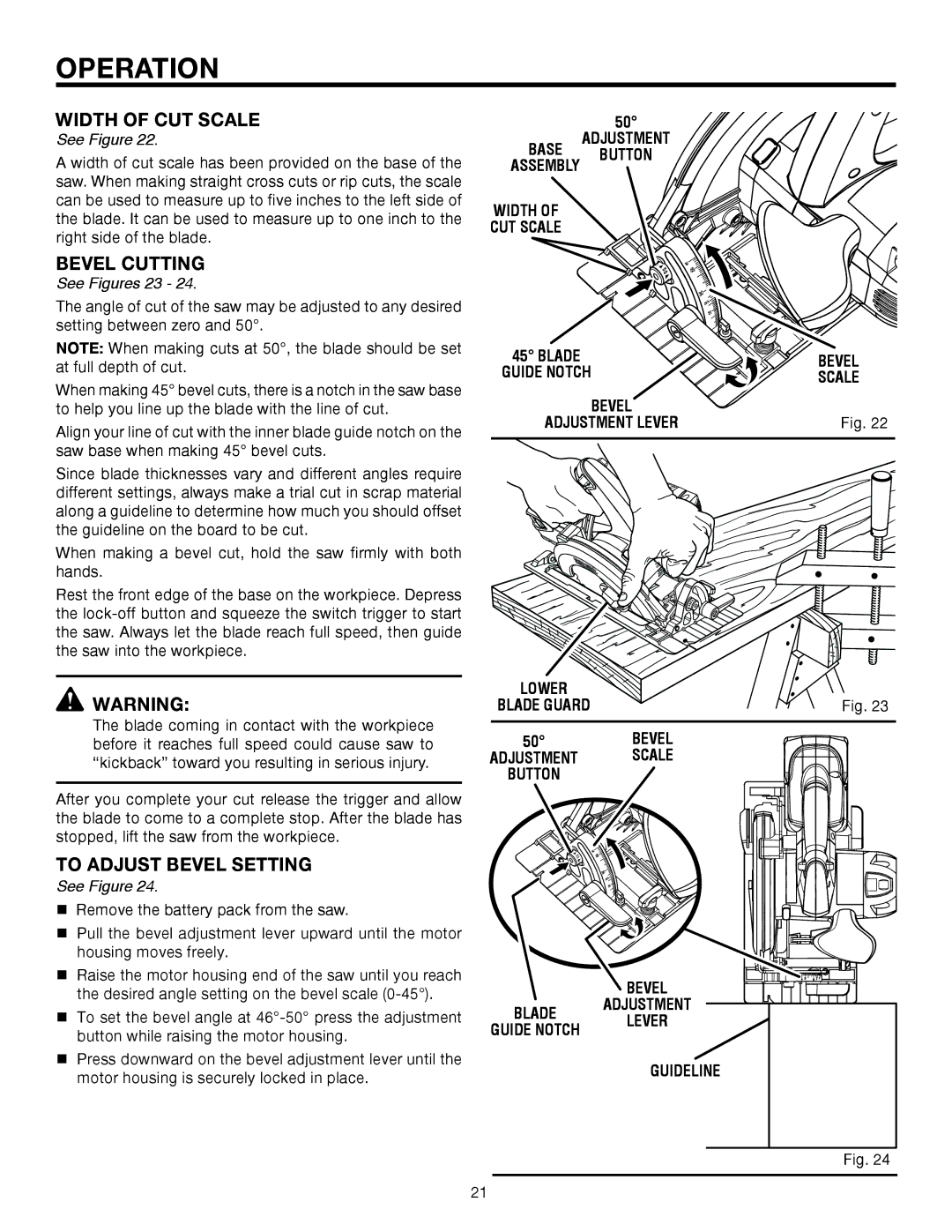
See Figure 22.
A width of cut scale has been provided on the base of the saw. When making straight cross cuts or rip cuts, the scale can be used to measure up to five inches to the left side of the blade. It can be used to measure up to one inch to the right side of the blade.
BEVEL CUTTING
See Figures 23 - 24.
The angle of cut of the saw may be adjusted to any desired setting between zero and 50°.
NOTE: When making cuts at 50°, the blade should be set at full depth of cut.
When making 45° bevel cuts, there is a notch in the saw base to help you line up the blade with the line of cut.
Align your line of cut with the inner blade guide notch on the saw base when making 45° bevel cuts.
Since blade thicknesses vary and different angles require different settings, always make a trial cut in scrap material along a guideline to determine how much you should offset the guideline on the board to be cut.
When making a bevel cut, hold the saw firmly with both hands.
Rest the front edge of the base on the workpiece. Depress the
![]() WARNING:
WARNING:
The blade coming in contact with the workpiece before it reaches full speed could cause saw to “kickback” toward you resulting in serious injury.
After you complete your cut release the trigger and allow the blade to come to a complete stop. After the blade has stopped, lift the saw from the workpiece.
TO ADJUST BEVEL SETTING
See Figure 24.
Remove the battery pack from the saw.
Pull the bevel adjustment lever upward until the motor housing moves freely.
Raise the motor housing end of the saw until you reach the desired angle setting on the bevel scale
To set the bevel angle at
Press downward on the bevel adjustment lever until the motor housing is securely locked in place.
| 50° | |
BASE | ADJUSTMENT | |
BUTTON | ||
ASSEMBLY | ||
| ||
WIDTH OF |
| |
CUT SCALE |
|
![]()
![]() 0
0 ![]()
5
0 ![]()
![]()
![]()
![]()
![]()
![]()
![]()
![]() 5
5![]()
![]()
45° BLADE | BEVEL | |
GUIDE NOTCH | ||
SCALE | ||
| ||
BEVEL |
| |
ADJUSTMENT LEVER | Fig. 22 |
![]() 5 50
5 50 ![]()
![]()
| 0 |
LOWER |
|
BLADE GUARD | Fig. 23 |
50° | BEVEL |
ADJUSTMENT | SCALE |
BUTTON |
|
![]() 0
0 ![]()
5
0
5![]()
![]()
| BEVEL | |
BLADE | ADJUSTMENT | |
LEVER | ||
GUIDE NOTCH | ||
| ||
| GUIDELINE |
Fig. 24
21