Battery and Charging
Amplifiers will put an increased load on the vehicle's battery and charging system. We recommend checking your alternator and battery condition to ensure that the electrical system has enough capacity to handle the increased load of your stereo system. Stock electrical systems which are in good condition should be able to handle the extra load of any Rockford amplifier without problems, although battery and alternator life can be reduced slightly. To maximize the performance of your Rockford Fosgate amplifier, we suggest the use of a heavy duty battery and an energy storage capacitor.
Wiring the System
CAUTION: Avoid running power wires near the low level input cables, antenna, power leads, sensitive equipment or harnesses. The power wires carry sub- stantial current and could induce noise into the audio system.
1.Plan the wire routing. Take care when running signal level RCA cables to keep them close together but isolated from the amplifier's power cables and any high power auto accessories, especially electric motors. This is done to prevent coupling the noise from radiated electrical fields into the audio signal. When feeding the wires through the firewall or any metal barrier, protect them with plastic or rubber grommets to pre- vent short circuits. Leave the wires long at this point to adjust for a pre- cise fit at a later time.
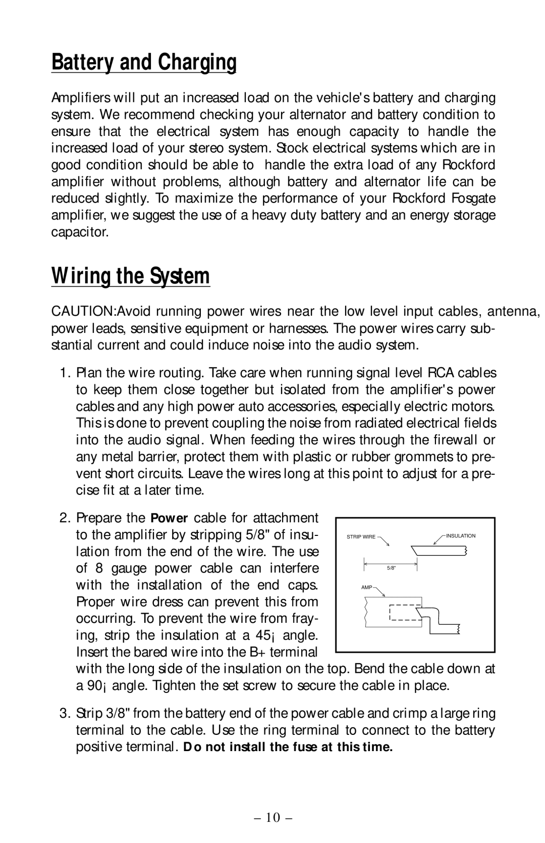
2.Prepare the Power cable for attachment
to the amplifier by stripping 5/8" of insu- | STRIP WIRE |
|
| INSULATION | ||
lation from the end of the wire. The use | > |
| > | |||
|
|
|
|
|
| |
of 8 gauge power cable can interfere |
| < |
| > |
|
|
| 5/8" |
|
|
| ||
|
|
|
|
|
| |
with the installation of the end caps. | AMP |
|
|
| ||
Proper wire dress can prevent this from | > |
|
|
|
| |
|
|
|
|
|
| |
occurring. To prevent the wire from fray- |
|
|
|
|
|
|
|
|
|
|
|
| |
ing, strip the insulation at a 45° angle. |
|
|
|
|
|
|
Insert the bared wire into the B+ terminal |
|
|
|
|
|
|
|
|
|
|
|
| |
with the long side of the insulation on the top. Bend the cable down at a 90° angle. Tighten the set screw to secure the cable in place.
3.Strip 3/8" from the battery end of the power cable and crimp a large ring terminal to the cable. Use the ring terminal to connect to the battery positive terminal. Do not install the fuse at this time.
– 10 –