4. INSTALLATION
4.4Printer (NX-700B only)
Prepare the printer by locally as shown below for the NX-700B.
-8 bit parallel Centronics interface, or serial RS-232C -Serial printer
-Baud Rate: 9600 bps
-Character length: 8 bit
-Parity: No
-Flow control: Xon/Xoff
-32 characters/line or more
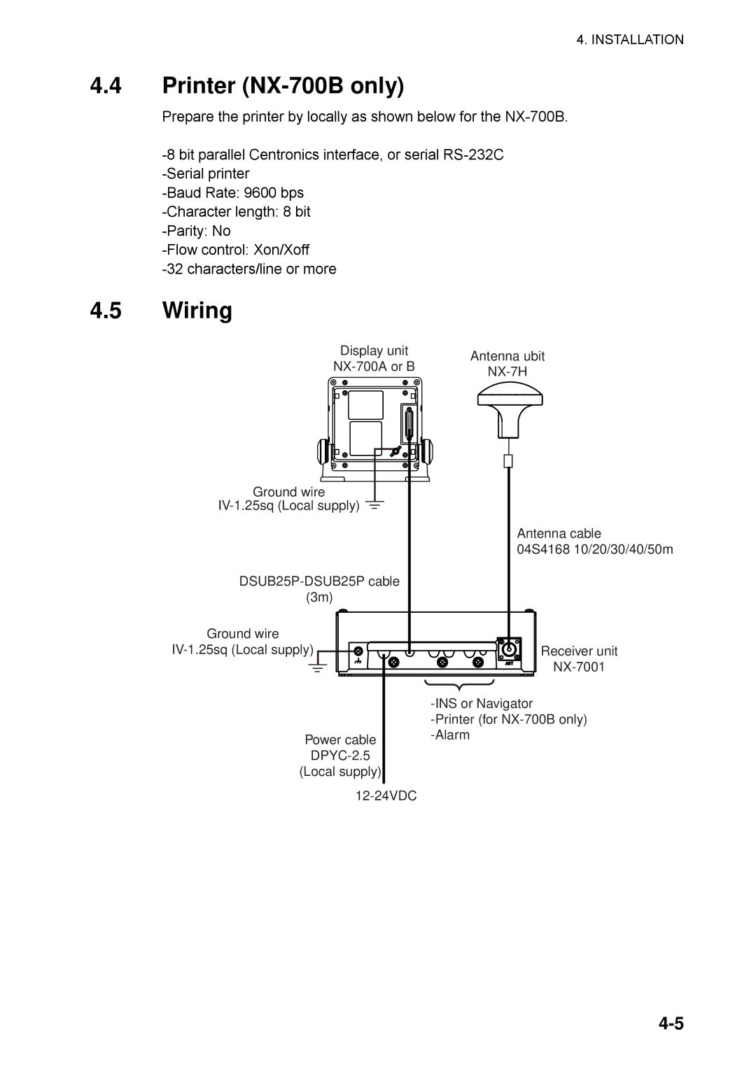
4.5Wiring
| Display unit | Antenna ubit |
| NX-700A or B |
| NX-7H |
| |
Ground wire
IV-1.25sq (Local supply) 
DSUB25P-DSUB25P cable
(3m)
Ground wire
IV-1.25sq (Local supply)
Power cable
DPYC-2.5
(Local supply)
12-24VDC
Antenna cable
04S4168 10/20/30/40/50m
Receiver unit
NX-7001
-INS or Navigator
-Printer (for NX-700B only) -Alarm